


Installation and Turn-up
950-779-115-02, Revision 02
4
March 17, 2000
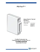
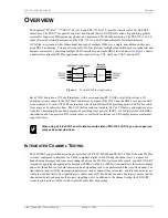
PRL-770 and PRL-779 List 1E and 2E
I
NSTALLATION
AND
T
URN
-
UP
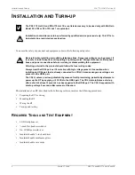
To ensure the safety of personnel and equipment, observe the following safety rules:
The installation of an RT, described in the following sections, involves the following procedures:
•
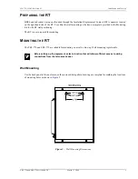
Preparing the RT for wiring
•
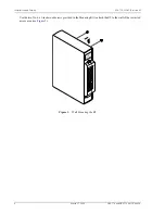
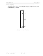
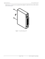
Mounting the RT
•
Wiring the RT
•
Turn-up and testing
R
EQUIRED
T
OOLS
AND
T
EST
E
QUIPMENT
•
LS/GS telephone set
•
1
/
4
-inch flat-head screwdriver
•
No. 1 Phillips screwdriver
•
Insulated-handle
3
/
8
-inch nut driver
•
Insulated-handle needlenose pliers
•
Insulated-handle wire cutter
The PRL-770 List 2 E and PRL-779 List 1 E are a listed accessory to be used only with PairGain
Model PLL-729 or PLL-735 List 1 or equivalent.
Installation and maintenance to be performed by qualified service personnel only. This RT is to
be installed in a restricted access location.
Be careful when installing or modifying telephone lines. Dangerous voltages can be present. It
is unsafe to install telephone wiring during a lightning storm. Always disconnect all telephone
lines and power connections before servicing or disassembling this equipment.
All wiring external to the product should follow the local wiring codes.
Always treat the HDSL pair as if it were live with high voltage present. Use caution when
installing an HDSL pair that is already connected to a COLU, because dangerous voltages are
present on the HDSL pair.
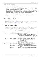
The COLU, unless previously disabled by means of craft provisioning, periodically attempts to
power up the RT by ap/-130 Vdc to the HDSL pair. The COLU also initiates a start-up
after a short of at least 3 seconds has been applied to the HDSL pair. The COLU responds with
start-up voltage 3 seconds after removal of the short.


