

950-779-115-02, Revision 02
Fault Isolation
PRL-770 and PRL-779 List 1E and 2E
March 17, 2000
13
S
UBSCRIBER
R
EPORTED
F
AULTS
Use the craft interface to initiate a subscriber drop test to determine the cause of any of the following problems.
The subscriber drop test performs Hazardous Potential, Foreign Voltage, Resistive Faults, Receiver Off-Hook,
and Ringers Tests.
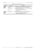
provides procedures for isolating faults, based on subscriber reports.
M
argin
Flashing
•
distance limitation exceeded
1
Initial installation, check engineering records for distance between COT
shelf and RT.
•
fault in HDSL line
2
If existing installation, measure loss of HDSL line to ensure that the
maximum attenuation value has not been exceeded.
•
faulty RT
3
Replace the COLU or the RT or both.
SYNC
Off
•
HDSL line has lost
synchronization
1
Initial installation, check engineering records for distance between COT
shelf and RT.
•
distance limitation may have
been exceeded
2
If existing installation, measure loss of HDSL line to ensure that the
maximum attenuation value has not been exceeded.
•
COLU is faulty
3
Replace the COLU or the RT or both.
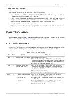
PWR
Off
•
no input power
1
Ground fault condition exists.
•
on-board fuse is blown on
COLU
2
Check input COT power at COT shelf backplane with COLU removed.
3
If power is present at COT shelf backplane, replace the COLU.
PWR
Flashing
•
HDSL line open
1
Check line continuity and resistance.
•
an overload exists
2
COLU power supply or RT may be faulty.
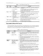
Table 2.
Subscriber Fault Isolating
Conditions
Causes
Procedures
no dial tone,
cannot dial
•
Short-circuit or
open-circuit
1
At the CO using the craft interface, select Test menu option, and view the test
results. The tests run are for Hazardous Potential, Foreign Voltage, Resistive
Fault, and CPE Termination.
•
faulty COLU or RT
2
Check for shorts or opens towards the subscriber or on the customer
premise.
3
Lift the jumper in the CO between the CO switch and the COT shelf. If dial tone
is present at the switch, replace the COLU.
4
If after replacing the COLU the dial tone is still not present, the fault is in the
RT. Replace the RT.
Phone does
not ring
•
high-resistance short on
subscriber drop (REN load
exceeded, see
Specifications)
1
At the CO, using the craft interface, go to the COLU Main screen to verify the
correct operation of the COLU. If you cannot view the COLU Main screen, a
communication error exists indicating a faulty COLU. Remove and re-insert
the COLU.
•
faulty RT or COLU
2
Go to the Test menu option, and select the desired circuit to test.
3
View the subscriber drop test results. Refer to the Test Submenu section for
specific results.
4
Check for ringing on another line terminated on the same RT. If ringing is
present on other lines, check for high-resistance shorts on the subscriber
drop. If no high resistance shorts, replace the RT.
5
If ringing is not present on another circuit terminated on the RT, lift the jumper
between the CO switch and the COT shelf. If ringing is present, replace the
COLU. If ringing is not present, the fault is in the switch.
Table 1.
COLU LED Fault Isolating (Cont.)
LED
Mode
Condition
Procedure


