background image

950-779-115-02, Revision 02


Overview

PRL-770 and PRL-779 List 1E and 2E

March 17, 2000

 1

O

VERVIEW

The PairGain

®

 PG-Flex

Plus 

™ PRL-770 List 2 E and PRL-779 List 1 E, provides interfaces for LS/GS POTS 

subscribers. The PRL-779 supports Loop Start and Ground Start (LS/GS) POTS, allows Tip and Ring polarity 
reversal for support of Millennium pay phones, and implements TR-08 channel testing. The PRL-770 is a 4 LS 
Indoor Remote Terminal Enclosure, and the PRL-779 is a 6 LS/GS Indoor Remote Terminal Enclosure.

A PG-Flex

Plus


system provides bidirectional transport of multiple DS0s over a single, unconditioned wire pair 

using HDSL technology. Using an existing cable, PG-Plus provides for higher bandwidth needs of residential and 
business customers by providing multiple LS/GS interfaces on a single HDSL twisted-pair wire. 
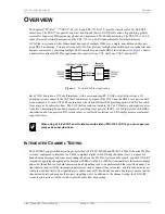
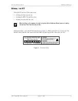
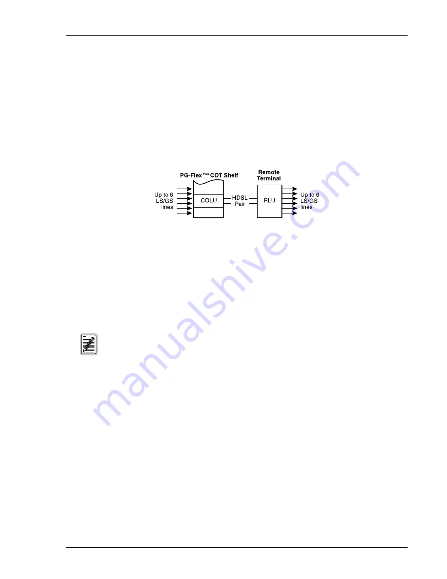
Figure 1

 shows 

a minimally configured PG-Plus application that consists of one COT shelf, one COLU, and one RT.

Figure 1.

Typical PG-Plus Application

Each COLU housed in a COT shelf interfaces with a corresponding RT. LS/GS or digital lines from a CO 
switching system connect to the COT shelf and are sent by means of the COLU and the HDSL wire pair to an RT. 
As an example, a 23-inch COT shelf can interface with sixteen different RTs providing up to six LS/GS lines each, 
for as many as 96 subscriber lines. The COT shelf operates on standard -48 Vdc CO battery and supplies power 
to the RT, eliminating the need and expense of providing local power at the RT. A PG-Plus system with HDSL 
transmission and line-powered RTs results in fast, cost-effective solutions to LS/GS deployment over minimal 
copper facilities.

I

NTEGRATED

 C

HANNEL

 T

ESTING

The LS/GS RT supports channel testing as described in TR-TSY-000008 and TR-TSY-000465 when the PG-Plus 
system is configured to interface to a TR-08 compliant digital switch. During the channel test, a sequence of 
hand-shaking messages and tones are exchanged between the PG-Plus system and the switch, and the LS/GS RT 
responds by applying the appropriate absorptive (600 

) or reflective (0 ) test terminations to the remote channel 

under test, thus allowing for both transmission and signalling tests to be performed on that specific channel. The 
transmission tests verify the transmission parameters, such as channel loss, return loss, and idle channel noise are 
within the required limits. The signalling tests, that consist of off-hook detection and a ringing test, ensure that the 
channel can detect and produce the correct signalling states. In addition to the channel testing, the LS/GS RT 
works in conjunction with the switch to provide subscriber drop testing.

When using a 23-inch COT shelf to interface with sixteen PRL-770 4 LS RTs you can support as 
many as 64 subscriber lines.

Summary of Contents for 150-1670-52

Page 1: ...ENGINEERING SERVICES TECHNICAL PRACTICE 950 779 115 020 SECTION 950 779 115 02 Indoor Remote Terminal Enclosure PRL 770 List 2E PRL 779 List 1E Part Number 150 1670 52 150 1679 51 CLEI Code S9MSBA0A...

Page 2: ...ll assert no such right license or interest with respect to such trademark All other product names mentioned in this document are used for identification purposes only and may be trademarks or registe...

Page 3: ...y and to PairGain Order replacement equipment if necessary Check the packing list to ensure complete and accurate shipment of each listed item If the shipment is short or irregular contact PairGain as...

Page 4: ...Inspecting Your Shipment 950 779 115 02 Revision 02 iv March 17 2000 PRL 770 and PRL 779 List 1E and 2E...

Page 5: ...t Equipment 4 Preparing the RT 5 Mounting the RT 5 Wall Mounting 5 Line up Mounting 7 Wiring the RT 9 Turn up and Testing 12 Fault Isolation____________________________________________________________...

Page 6: ...Table of Contents 950 779 115 02 Revision 02 vi March 17 2000 PRL 770 and PRL 779 List 1E and 2E...

Page 7: ...LS GS lines each for as many as 96 subscriber lines The COT shelf operates on standard 48 Vdc CO battery and supplies power to the RT eliminating the need and expense of providing local power at the...

Page 8: ...d to establish a path to channel 1 of the LS GS RT during fault conditions and to provide for drop testing of the selected subscriber line from the CO location SPECIFICATIONS Power Voltage Safety A2 c...

Page 9: ...oop Current 23 mA minimum Ring Generation PRL 770 Balanced Trapezoidal 40 Vrms minimum 20 3 Hz up to 5 REN per line 10 REN total at RT PRL 779 Unbalanced Trapezoidal 40 Vrms minimum 20 3 Hz up to 5 RE...

Page 10: ...performed by qualified service personnel only This RT is to be installed in a restricted access location Be careful when installing or modifying telephone lines Dangerous voltages can be present It is...

Page 11: ...e Mounting Kit for the RT wall positioning The RT is now prepared for mounting MOUNTING THE RT The PRL 770 and PRL 779 are suitable for mounting on a wall or line up Wall mounting is preferable Wall M...

Page 12: ...2 6 March 17 2000 PRL 770 and PRL 779 List 1E and 2E Use the two No 6 x 1 inch wood screws provided in the Mounting Kit to attach the RT to the wall of the restricted access area see Figure 3 Figure 3...

Page 13: ...L 770 and PRL 779 List 1E and 2E March 17 2000 7 Line up Mounting Use the back panel of the enclosure or the enclosed hole pattern drawing as a template for marking the locations of mounting holes as...

Page 14: ...8 March 17 2000 PRL 770 and PRL 779 List 1E and 2E Use the two No 6 x 1 inch wood screws provided in the Mounting Kit to attach the RT to the side of the restricted access area see Figure 5 Figure 5 L...

Page 15: ...ip and Ring wires attaching the subscriber line wires During installation refer to the RT Reference label see Figure 6 affixed inside the Telco Access door The Reference label identifies the Frame Gro...

Page 16: ...nsert the Tip and Ring wires through the hole below the Telco Access door This RT does not provide primary protectors on the HDSL or subscriber pairs The primary protection for HDSL pairs must be an i...

Page 17: ...g holes see Figure 8 Each wire entry hole accepts one unstripped solid copper wire 22 24 American Wire Gauge AWG with a maximum insulation diameter of 1 52 mm Figure 8 Attaching the RT Wires 4 Press t...

Page 18: ...to determine the cause of any of the following problems Table 1 provides procedures for isolating faults indicated by the COLU LEDs Table 1 COLU LED Fault Isolating LED Mode Condition Procedure None O...

Page 19: ...y be faulty Table 2 Subscriber Fault Isolating Conditions Causes Procedures no dial tone cannot dial Short circuit or open circuit 1 At the CO using the craft interface select Test menu option and vie...

Page 20: ...hone loop length too long 2 If phone does not stop ringing when using a butt set at the subscriber location one or both of these conditions exist faulty RT loop length is too long refer to Specificati...

Page 21: ...Central Office Terminal ESD Electrostatic Discharge HDSL High bit rate Digital Subscriber Line IDC Insulation Displacement Contact LED Light emitting Diode LS GS Loop Start and Ground Start MLT Mechan...

Page 22: ...ts will operate substantially in accordance with the PairGain published specifications and documentation for such software PairGain s entire liability for software that does not comply with the forego...

Page 23: ...y PairGain the Buyer will be responsible for payment of the cost of the replacement product BILLING PairGain s repair of products returned for repair replacement or credit whether in warranty or out o...

Page 24: ...ason for the return For example The equipment needs an ECO ECN upgrade The equipment is defective If there is another reason for returning the equipment please let us know so we can determine how best...

Page 25: ...se harmful interference to radio communications Operation of this equipment in a residential area is likely to cause harmful interference in which case the user will be required to correct the interfe...

Page 26: ...Corporate Office 14402 Franklin Avenue Tustin CA 92780 Tel 714 832 9922 Fax 714 832 9924 For Technical Assistance 800 638 0031 714 730 3222...

Reviews: