2C9-2
1-5-28
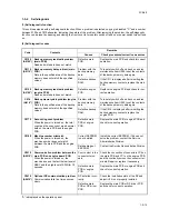
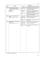
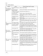
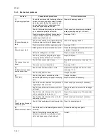
1-5-4 Electric problems
Problem
Causes
Check procedures/corrective measures
(1)
The machine does
not operate when the
power switch is
turned on.
No electricity at the power
outlet.
Measure the input voltage.
The power cord is not
plugged in properly.
Check the contact between the power plug and the outlet.
The front cover or left cover
is not closed completely.
Check the front cover and left cover.
Broken power cord.
Check for continuity. If none, replace the cord.
Defective power switch.
Check for continuity across the contacts. If none, replace the
power switch.
Blown fuse in the power
source PCB.
Check for continuity. If none, remove the cause of blowing and
replace the fuse.
Defective front or left cover
safety switch.
Check for continuity across the contacts of each switch. If none,
replace the switch.
Defective power source
PCB.
With AC present, check for 24 V DC at YC1-1 and 5 V DC at YC1-
7 on the power source PCB. If none, replace the power source
PCB.
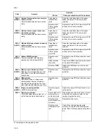
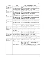
(2)
The drive motor does
not operate
(C2000).
Poor contact in the drive
motor connector terminals.
Reinsert the connector. Also check for continuity within the con-
nector cable. If none, remedy or replace the cable.
Broken drive motor gear.
Check visually and replace the drive motor if necessary.
Defective drive motor.
Run maintenance item U030 and check if the drive motor oper-
ates when YC7-5 on the engine PCB goes low. If not, replace the
drive motor.
Defective engine PCB.
Run maintenance item U030 and check if YC7-5 on the engine
PCB goes low. If not, replace the engine PCB.
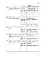
(3)
The registration
motor does not oper-
ate.
Poor contact in the registra-
tion motor connector termi-
nals.
Reinsert the connector. Also check for continuity within the con-
nector cable. If none, remedy or replace the cable.
Broken registration motor
gear.
Check visually and replace the registration motor if necessary.
Defective registration
motor.
Run maintenance item U030 and check if the registration motor
operates when YC2-1,2,4,5 on the registration motor PCB goes
low. If not, replace the registration motor.
Defective engine PCB.
Run maintenance item U030 and check if YC4-4 on the engine
PCB goes low. If not, replace the engine PCB.
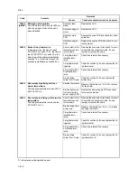
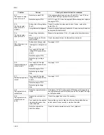
(4)
The exit motor does
not operate.
Poor contact in the exit
motor connector terminals.
Reinsert the connector. Also check for continuity within the con-
nector cable. If none, remedy or replace the cable.
Broken exit motor gear.
Check visually and replace the exit motor if necessary.
Defective exit motor.
Run maintenance item U030 and check if the exit motor operates
when YC14-1,2,3,4 on the engine PCB go low. If not, replace the
exit motor.
Defective engine PCB.
Run maintenance item U030 and check if YC14-1,2,3,4 on the
engine PCB go low. If not, replace the engine PCB.
Summary of Contents for CS-1620
Page 1: ...SERVICE MANUAL Published in June 05 2C970946 Revision 6 CS 1620 2020...
Page 4: ...This page is intentionally left blank...
Page 10: ...This page is intentionally left blank...
Page 48: ...2C9 4 1 4 7 This page is intentionally left blank...
Page 61: ...2C9 4 1 4 18 This page is intentionally left blank...
Page 73: ...2C9 4 1 4 28 This page is intentionally left blank...
Page 84: ...2C9 4 1 4 37 This page is intentionally left blank...
Page 94: ...2C9 4 1 4 45 This page is intentionally left blank...
Page 147: ...2C9 4 1 6 16 This page is intentionally left blank...
Page 173: ...2C9 6 0 1 6 40 This page is intentionally left blank...
Page 235: ......


