2C9
1-3-16
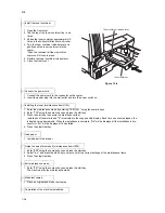
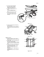
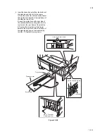
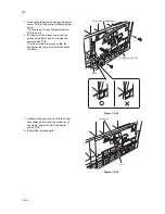
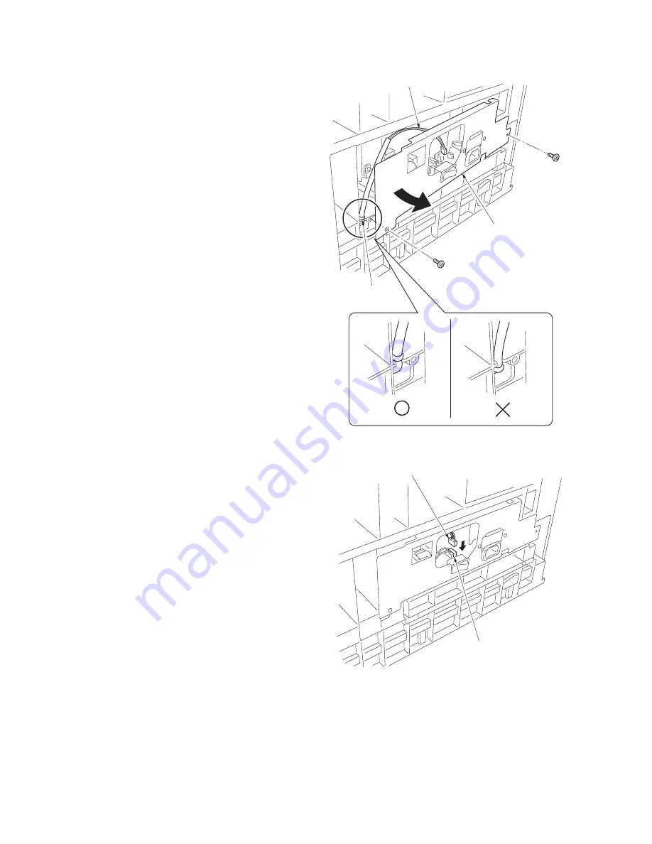
5. Remove the two screws and open the power
source PCB in the direction indicated by the
arrow.
* Take care not to open the power source
PCB too much.
6. Fit the wire of the drawer heater into the
groove of the frame and put it inside the
power source PCB.
* Fit the wire into the groove so that the
band mounted to the wire is located above
the frame.
Figure 1-3-29
7. Reattach the power source PCB to its origi-
nal position and connect the connector of
the drawer heater to YC8 of the power
source PCB.
8. Refit all the removed parts.
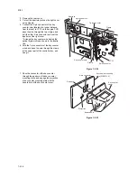
Figure 1-3-30
Power source PCB
Wire of the drawer heater
Band
YC8
Connector
Summary of Contents for CS-1620
Page 1: ...SERVICE MANUAL Published in June 05 2C970946 Revision 6 CS 1620 2020...
Page 4: ...This page is intentionally left blank...
Page 10: ...This page is intentionally left blank...
Page 48: ...2C9 4 1 4 7 This page is intentionally left blank...
Page 61: ...2C9 4 1 4 18 This page is intentionally left blank...
Page 73: ...2C9 4 1 4 28 This page is intentionally left blank...
Page 84: ...2C9 4 1 4 37 This page is intentionally left blank...
Page 94: ...2C9 4 1 4 45 This page is intentionally left blank...
Page 147: ...2C9 4 1 6 16 This page is intentionally left blank...
Page 173: ...2C9 6 0 1 6 40 This page is intentionally left blank...
Page 235: ......

