background image

2C9

1-4-29

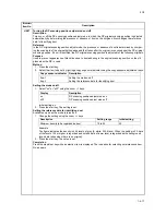
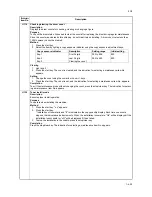
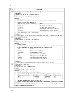
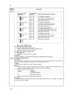
U203

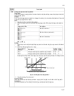
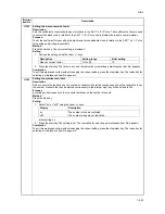
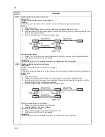
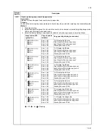
Operating DP separately
Description

Simulates the original conveying operation separately in the DP. 

Purpose

To check the DP.

Method

1. Press the start key.
2. Place an original in the DP if running this simulation with paper.
3. Select the item to be operated using the copy exposure adjustment keys.

4. Press the start key. The operation starts.
5. To stop continuous operation, press the stop/clear key.

Completion

Press the stop/clear key when the operation stops. The indication for selecting a maintenance item No. 
appears.

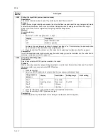
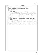
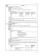
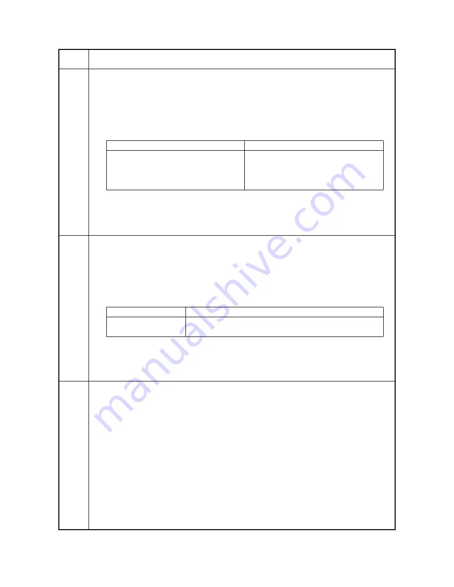
U204

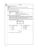
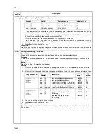
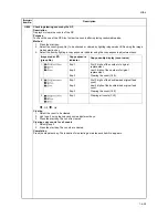
Setting the presence or absence of a key card or key counter
Description

Sets the presence or absence of the optional key card or key counter.

Purpose

To run this maintenance item if a key card or key counter is installed.

Method

Press the start key.

Setting

1. Select either "on" or "oFF" using the zoom +/- keys.

Initial setting: oFF

2. Press the start key. The setting is set and the indication for selecting a maintenance item No. appears. 

Completion

To exit this maintenance item without changing the current setting, press the stop/clear key. The indication for 
selecting a maintenance item No. appears.

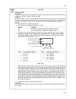
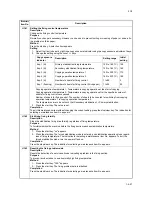
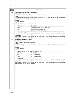
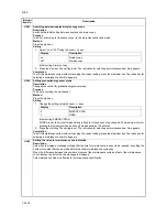
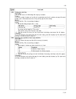
U207

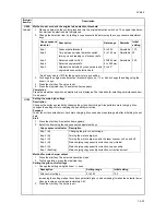
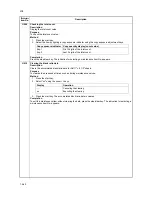
Checking the operation panel keys
Description

Checks operation of the operation panel keys.

Purpose

To check operation of all the keys and LEDs on the operation panel.

Method

1. Press the start key.
2. "1" appears on the copy quantity display and the leftmost LED on the operation panel lights.
3. As the keys on the operation panel are pressed in order from the left to right, the figure shown on the 

copy quantity display increases in increments of 1. If there is an LED corresponding to the key pressed, 
the LED will light.

4. When all the keys on the operation panel have been pressed, all the LEDs light for up to 10 seconds.
5. When the LEDs go off, press the start key. All the LEDs light for 10 seconds again.

Completion

Press the stop/clear key. The indication for selecting a maintenance item No. appears.

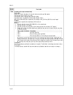
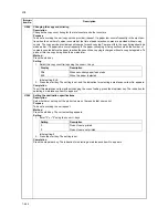
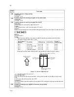
Maintenance

item No.

Description

Display (copy exposure indicator)

Operation

d-P (exp. 1)

With paper

d-n (exp. 2)

Without paper (continuous operation)

dp2 (exp. 3)

With paper (duplex mode)

dn2 (exp. 4)

Without paper (duplex mode)

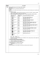
Display

Description

oFF

None

on

The key card or key counter is installed

Summary of Contents for CS-1620

Page 1: ...SERVICE MANUAL Published in June 05 2C970946 Revision 6 CS 1620 2020...

Page 2: ...URER DISPOSE OF USED BATTERIES ACCORDING TO THE MANUFACTURER S INSTRUCTIONS ATTENTION IL Y A DANGER D EXPLOSION S IL Y A REMPLACEMENT INCORRECT DE LA BATTERIE REMPLACER UNIQUEMENT AVEC UNE BATTERIE DU...

Page 3: ...e 14 2005 Contents 1 1 1 1 2 2 1 3 5 1 3 9 1 3 11 1 3 12 1 3 13 1 4 2 1 4 3 1 4 4 1 4 16 1 1 4 20 1 4 23 1 4 26 1 5 3 1 5 4 1 5 5 1 5 9 1 5 10 1 5 11 1 5 12 1 5 15 1 5 17 1 5 25 1 5 29 1 5 32 1 6 7 1...

Page 4: ...This page is intentionally left blank...

Page 5: ...sonnel to ensure the safety of their customers their machines as well as themselves during maintenance activities Service personnel are advised to read this booklet carefully to familiarize themselves...

Page 6: ...this symbol CAUTION Bodily injury or damage to property may result from insufficient attention to or incorrect compliance with warning messages using this symbol Symbols The triangle symbol indicates...

Page 7: ...or dusty place This may cause fire or electric shock Do not install the copier near a radiator heater other heat source or near flammable material This may cause fire Allow sufficient space around the...

Page 8: ...carefully Always check that the copier is correctly connected to an outlet with a ground connection Check that the power cable covering is free of damage Check that the power plug is dust free If it i...

Page 9: ...trapped wire and missing screws Check that all the caution labels that should be present on the machine according to the instruction handbook are clean and not peeling Replace with new ones if necess...

Page 10: ...This page is intentionally left blank...

Page 11: ...er management 1 4 45 1 Using the copier management mode 1 4 45 2 Setting department management items 1 4 46 3 Copy default 1 4 46 1 5 Troubleshooting 1 5 1 Paper misfeed detection 1 5 1 1 Paper misfee...

Page 12: ...d paper conveying or fixing section is indicated when the power switch is turned on 1 5 31 23 The message requesting covers to be closed is displayed when the front cover and left cover are closed 1 5...

Page 13: ...unit 1 6 38 2 Detaching and refitting the press roller 1 6 39 3 Detaching and refitting the fixing heater M and S 1 6 40 4 Detaching and refitting the heat roller separation claws 1 6 41 5 Detaching a...

Page 14: ...CB 2 3 14 2 3 5 CCD PCB 2 3 17 2 4 Appendixes Timing chart No 1 2 4 1 Timing chart No 2 2 4 2 Timing chart No 3 2 4 3 Timing chart No 4 2 4 4 Chart of image adjustment procedures 2 4 5 Maintenance par...

Page 15: ...ies min 8 1 2 x 14 11 copies min First copy time Approximately 5 9 s A4 11 x 8 1 2 Warm up time Less then 19 8 s room temperature 20 C 68 F 50 RH Paper feed system Automatic feed Capacity Drawers 300...

Page 16: ...margin Border width Aggre gate copy Sort copy Eco copy Copy program and Section management mode Power source 120 V AC 60 Hz 9 0 A 220 240 V AC 50 Hz 5 0 A Average Options Document processor paper fee...

Page 17: ...peration panel 4 Drawer 5 Width guide 6 Length guide 7 Left cover handle 8 Bypass tray 9 Support guide 10 Slider 11 Contact glass 12 Original size indicator plate 13 Left cover 14 Waste toner box 15 T...

Page 18: ...uantity magnification display 14 Zoom key 15 Zoom key 16 Recall Enter key 17 Magnification Select key 18 Paper Select key 19 Paper supply indicator 20 Paper supply level indicator 21 Paper jam indicat...

Page 19: ...ion Figure 1 1 3 Machine cross section Light path Paper path 1 Paper feed section 2 Optical section 3 Drum section 4 Developing section 5 Transfer and separation section 6 Fixing section 7 Exit and sw...

Page 20: ...32 6 Gear 25 7 Gear 25 8 Gear 20 9 Paper feed clutch gear 10 Gear 30 11 Gear 31 12 Gear 25 13 Gear 49 14 Gear 30 23 15 Developing gear 25 16 Developing gear 26 17 Fixing joint gear 29 18 Gear 40 19 G...

Page 21: ...ture between 20 C 4 F and 55 C 131 F and at a relative humidity not higher than 90 RH Avoid abrupt changes in temperature and humidity Avoid exposure to any substance which is harmful to or may affect...

Page 22: ...bration Choose a surface capable of supporting the weight of the machine Place the machine on a level surface maximum allowance inclination 1 Avoid air borne substances that may adversely affect the m...

Page 23: ...the tapes and pins Install the original cover or the optional DP Connect the power cord Load paper Make test copies Output an own status report maintenance item U000 Exit maintenance mode Start Instal...

Page 24: ...Lower left pad 6 Lower right pad 7 Upper left pad 8 Upper right pad 9 Inner frame 10 Left spacer 11 Rear spacer 12 Rear pad 13 Skid 14 Belt 15 Eject sheet 16 Machine cover 17 Bar code labels 18 Top s...

Page 25: ...unit Figure 1 3 3 1 Install the original cover or optional DP see page 1 3 8 to 1 3 10 when installing the DP 1 Install the optional duplex unit as necessary see page 1 3 11 to 1 3 13 Install the opti...

Page 26: ...e item Installation of toner starts and 9 is indicated in the copy quantity display Each time one minute elapses the indicated value decrements When the installation is complete Gd will be displayed i...

Page 27: ...ounts Double count U254 Turning auto start function on off ON U255 Setting auto clear time 90s U258 Switching copy operation at toner empty detection SINGLE MODE U260 Changing the copy count timing Af...

Page 28: ...by aligning the positioning insertion sections of the first paper feeder with the positioning pins at the rear part of the second paper feeder Up to three paper feeders can be stacked Figure 1 3 6 2 I...

Page 29: ...s 2 and 3 until an adequate image is obtained Figure 1 3 8 Adjusting the center line 1 Run maintenance mode 034 Press the image quality mode key until Text and Photo are lit group 2 First paper feeder...

Page 30: ...em to the lower frame Figure 1 3 10 3 Place the DP on the copier by fitting the pins into the holes at the hinge sections of the DP and sliding them toward the front side Figure 1 3 11 4 Secure the DP...

Page 31: ...to the DP Figure 1 3 14 Operation check 1 Prepare an original on which 4 lines are drawn 15 mm from the edges and the center line is drawn 2 Set the original on the DP and make a test copy to check t...

Page 32: ...For copy example b decrease the value Changing the value by one moves the leading edge by 0 17 mm The larger the value the later the image scan start timing The smaller the value the earlier the image...

Page 33: ...move the stopper from the front side 5 Open the left cover until it is put horizontally Figure 1 3 19 6 Turn the wire guide section of the duplex unit in the direction indicated by the arrow Figure 1...

Page 34: ...igure 1 3 22 1 9 Hang the hook of the plate lock on the con veying unit and then turn the plate lock to fit the hole to the claw of the duplex unit Figure 1 3 22 2 10 Secure the duplex unit with the t...

Page 35: ...example b is obtained decrease the adjustment value Setting range 5 0 10 0 3 Make a test copy again 4 Repeat steps 2 and 3 until an adequate image is obtained Figure 1 3 25 Adjusting the center line 1...

Page 36: ...llowing parts Drawer heater P N 120 V specifications 2C960030 220 240 V specifications 2C960040 One 1 M4 x 10 tap tight S binding screw P N B3024100 Procedure 1 Remove the right cover 2 Pull out the d...

Page 37: ...he projections at the rear side of the cassette heater mounting plate into the two holes in the rear frame of the machine 3 Position the screw hole of the drawer heater to the screw hole of the front...

Page 38: ...ove of the frame and put it inside the power source PCB Fit the wire into the groove so that the band mounted to the wire is located above the frame Figure 1 3 29 7 Reattach the power source PCB to it...

Page 39: ...e 1 M3 bronze nut P N C2303000 Key counter mounting plate P N 2C960100 Key counter wire P N 2C960110 Procedure 1 Fit the key counter socket assembly to the key counter retainer using the two screws an...

Page 40: ...ire as shown in the illustra tion 6 Fold the 7 pin connector of the key counter wire back pass the wire through the clamp at the upper part of the controller box and hang it Figure 1 3 32 7 Pass the c...

Page 41: ...he rear cover Figure 1 3 34 12 Insert the key counter into the key counter socket assembly 13 Turn the main switch on and enter the main tenance mode 14 Run maintenance item U204 and select KEYCOUNTER...

Page 42: ...he numeric keys Enter 001 using the zoom keys or numeric keys and press the start key Enter the maintenance item number using the zoom keys or numeric keys The selected maintenance item is run Press t...

Page 43: ...on motor speed adjustment Motor speed adjustment for paper feed from bypass tray Motor speed adjustment for paper feed from optional paper feeder Motor speed adjustment in duplex mode 0 1 0 1 0 1 0 1...

Page 44: ...rol temperature Primary stabilization fixing temperature Secondary stabilization fixing temperature Copying operation temperature 1 Copying operation temperature 2 Number of sheets for fixing control...

Page 45: ...riginal from the DP U407 Adjusting the leading edge registration for memory image printing Other U901 Checking clearing copy counts by paper feed locations U903 Checking clearing the paper jam counts...

Page 46: ...cify the paper feed loca tion When output is complete the selected item appears Completion Press the stop clear key while a selection item is displayed The indication for selecting a maintenance item...

Page 47: ...item No Description Copy exposure indicator Copy quantity display Exp 1 lit 1st digit of machine number Exp 2 lit 2nd digit of machine number Exp 3 lit 3rd digit of machine number Exp 4 lit 4th digit...

Page 48: ...2C9 4 1 4 7 This page is intentionally left blank...

Page 49: ...item appears 7 To stop continuous operation press the stop reset key Completion Press the stop clear key while a selection item is displayed The indication for selecting a maintenance item No appears...

Page 50: ...etween respective machines i e settings for counters service call history and mode settings As a result initializes the backup RAM according to the specifications depending on the destination selected...

Page 51: ...per conveying operate correctly Method 1 Press the start key 2 Turn each switch on and off manually to check the status When the on status of a switch is detected the original size indicator correspon...

Page 52: ...To prevent the image at the trailing edge or right or left side of the paper from not being copied by setting the actual size of the folio paper used Method Press the start key Setting 1 Select the it...

Page 53: ...in the auxiliary scanning direction 4 Press the start key The value is set Interrupt copy mode While this maintenance item is being performed a VTC pattern shown below is output in interrupt copy mod...

Page 54: ...tion for selecting a maintenance item No appears Caution The following settings are also reset to the initial values by performing this maintenance item Exposure density gradient set in maintenance mo...

Page 55: ...canner magnification Adjustment See pages 1 6 28 and 29 U066 Adjusting the leading edge registration for scanning an original on the contact glass Adjustment See page 1 6 30 U067 Adjusting the center...

Page 56: ...keys First side Simplex or front side in duplex copying Second side Back side in duplex copying Increasing the setting makes the image longer and decreasing it makes the image shorter 3 Press the sta...

Page 57: ...The value is set Interrupt copy mode While this maintenance item is being performed copying from an original can be made in interrupt copy mode Adjustment 1 In interrupt copy mode make a copy using th...

Page 58: ...g moves the image to the right and decreasing it moves the image to the left 3 Press the start key The value is set Interrupt copy mode While this maintenance item is being performed copying from an o...

Page 59: ...iffers significantly between when scanning an original on the contact glass and when scanning an original from the DP Method Press the start key Setting 1 Change the setting using the zoom keys Increa...

Page 60: ...ment is complete Gd appears 4 Display each setting value after adjustment by lighting a copy exposure indicator using the copy expo sure adjustment keys If a problem occurs during auto adjustment nG i...

Page 61: ...2C9 4 1 4 18 This page is intentionally left blank...

Page 62: ...tem to be set by lighting a copy exposure indicator using the copy exposure adjustment keys Setting the mode on off 1 Select on or oFF using the zoom keys Initial setting on 2 Press the start key The...

Page 63: ...nce item without changing the current setting press the stop clear key The indication for selecting a maintenance item No appears U089 Outputting a MIP PG pattern Description Selects and outputs a MIP...

Page 64: ...rear indicates that scanner problem causes the fixing unevenness If the displayed results indicate no shading problems the fixing unevenness uneven copy density is caused by factors other than in the...

Page 65: ...ment by lighting a copy exposure indicator using the copy expo sure adjustment keys If a problem occurs during auto adjustment nG is displayed and operation stops Lighting the copy exposure indicator...

Page 66: ...ng makes the change in density larger and decreasing it makes the change smaller Figure 1 4 5 Exposure density gradient 3 Press the start key The value is set Test copy mode While this maintenance ite...

Page 67: ...taken at the nine points from 1 at the machine rear to 9 at the machine front is displayed The data is displayed within the range of 000 to 255 000 indicating white original present and 255 indicatin...

Page 68: ...he copy exposure adjustment keys Method for main charger output 1 Press the start key The selected operation starts 2 To stop operation press the stop clear key Setting the grid control voltage 1 Chan...

Page 69: ...hange the preset value Method Press the start key A selection item appears Setting 1 Select the group to be set or checked by lighting image mode LEDs using the image mode selection key 2 Select the i...

Page 70: ...ance item No appears Completion To exit the maintenance mode without changing the count press the stop clear key The indication for select ing a maintenance item No appears U130 Toner install mode Des...

Page 71: ...ss the start key 2 Select the item by lighting a copy exposure indicator using the copy exposure adjustment keys Clearing 1 Light exp 3 2 Press the start key The drive time is cleared and the indicati...

Page 72: ...he indication for selecting a maintenance item No appears Setting 1 1 Change the count using the numeric or zoom keys 2 2 Press the start key The count is set and the indication for selecting a mainte...

Page 73: ...2C9 4 1 4 28 This page is intentionally left blank...

Page 74: ...ization fixing drive forcibly regardless of fixing temperature Purpose To forcibly stabilize the machine before the fixing section reaches stabilization temperature Method 1 Press the start key on app...

Page 75: ...solute humidity Method 1 Press the start key 2 Display each temperature by lighting the respective copy exposure indicator using the copy exposure adjustment keys Completion Press the stop clear key T...

Page 76: ...without changing the current setting press the stop clear key The indication for selecting a maintenance item No appears U207 Checking the operation panel keys Description Checks operation of the oper...

Page 77: ...ce cycle Description Displays and changes the maintenance cycle Purpose To check and change the maintenance cycle Method 1 Press the start key The current setting is displayed 2 Select the item by lig...

Page 78: ...tem U020 Method Press the start key Setting 1 Select the destination using the zoom keys 2 Press the start key The setting is set and the machine automatically returns to the same status as when the p...

Page 79: ...No appears U254 Turning auto start function on off Description Selects if the auto start function is turned on Purpose Normally no change is necessary If incorrect operation occurs turn the function o...

Page 80: ...ithout changing the current setting press the stop clear key The indication for selecting a maintenance item No appears U258 Switching copy operation at toner empty detection Description Selects if co...

Page 81: ...1 Select the copy count timing using the zoom keys Initial setting EJE 2 Press the start key The setting is set and the indication for selecting a maintenance item No appears Completion To exit this m...

Page 82: ...ndication for selecting a maintenance item No appears U342 Setting the ejection restriction Description Sets or cancels the restriction on the number of sheets to be ejected continuously When the rest...

Page 83: ...GEEA is set the Auto off mode setting is fixed to ON and cannot be changed The maximum time for entering the low power mode and the off mode becomes 120 minutes 2 Press the start key The setting is s...

Page 84: ...2C9 4 1 4 37 This page is intentionally left blank...

Page 85: ...makes the margin narrower Figure 1 4 7 Correct margin amount 3 Press the start key The value is set Interrupt copy mode While this maintenance item is being performed copying from an original can be m...

Page 86: ...s 1 Select group 7 2 Press the start key The counts are cleared Completion Press the stop clear key The indication for selecting a maintenance item No appears Maintenance item No Description Image mod...

Page 87: ...atus by types Also to clear the service call code counts after replacing con sumable parts Method 1 Press the start key 2 Display the service call code to check the count using the copy exposure adjus...

Page 88: ...copy exposure adjustment keys 3 Press the start key The count is cleared Clearing copy counts for all counts 1 Select group 3 2 Press the start key The counts are cleared Completion Press the stop cle...

Page 89: ...data for A4 11 x 8 1 2 sheets Purpose To clear data as required at times such as during maintenance service Method 1 Press the start key 2 Select on using the zoom keys 3 Press the start key The accu...

Page 90: ...of B4 size copy count Last 3 digits of B4 size copy count Clearing the count CLE 3 Exp 1 lit Exp 2 lit Exp 3 lit Exp 4 lit A4 display the A4 size First 3 digits of A4 size copy count Last 3 digits of...

Page 91: ...Press the start key The accounting counter is cleared Completion To exit this maintenance item without clearing the data press the stop clear key The indication for selecting a maintenance item No app...

Page 92: ...ssette Purpose To be set according to user request Method Press the start key Setting 1 Select the magnification by lighting a copy exposure indicator using the copy exposure adjustment keys Initial s...

Page 93: ...tem No appears U990 Checking clearing the time for the exposure lamp to light Description Displays or clears the accumulated time for the exposure lamp to light Purpose To check duration of use of the...

Page 94: ...2C9 4 1 4 45 This page is intentionally left blank...

Page 95: ...inting adjustments used to check the machine status apart from that of the scanner with a non scanned output VTC PG pattern Method 1 Press the start key 2 Select the VTC PG pattern to be output using...

Page 96: ...ting a department management item Executing a default setting item Press both of the copy exposure adjustment keys and manegement key for 3 s Select an item using the zoom keys or numeric keys Press t...

Page 97: ...er on 1 Select F03 and press the enter key 2 Select the exposure mode and press the enter key Setting range 1 manual 2 auto Eco copy Selects the eco copy mode at power on 1 Select F04 and press the en...

Page 98: ...tomatically selected 1 Select F17 and press the enter key 2 Select the paper size and press the enter key Setting range AtC auto detection metric AtI auto detection inch o2r oficio2 Drawer paper size...

Page 99: ...dotted line Rotate sort Sets whether or not to perform rotate sorting when the sort mode is selected 1 Select F30 and press the enter key 2 Select ON or OFF and press the enter key Setting range ON en...

Page 100: ...be checked in maintenance item U903 To remove paper jammed in the copier open the front cover left cover or pull the drawer out To remove original jammed in the DP open the DP original cover Paper mis...

Page 101: ...2C9 3 1 5 2 2 Paper misfeed detection conditions Figure 1 5 2 ESW FSSW RSW PFCL RM DUPPCSW DUPFCL BYPPFSOL DPTSW OSBSW OCM OFM DPFCL1 DFSW1 DFSW2 DPFCL2 DPFCL3...

Page 102: ...eeder The drawer feed switch 2 DFSW2 does not turn on within 2490 ms of the drawer paper feed clutch 3 DPFCL3 turning on the clutch is then successively held off for 1 s and turned back on once but th...

Page 103: ...e fixing section paper feed from third paper feeder The exit switch ESW does not turn on within 3020 ms of the registration motor RM turning on 45 Misfeed in the fixing section paper feed from duplex...

Page 104: ...SW turning off DP 70 No original feed During the primary feed of the second original in the single sided or double sided original mode even if retry operation is performed five times primary original...

Page 105: ...ration switch actuator Check visually and replace registration switch if its actuator is bro ken Defective registration switch Run maintenance item U031 and turn registration switch on and off manuall...

Page 106: ...d pulley in the second paper feeder is deformed Check visually and replace any deformed pulley Broken drawer feed switch 1 actuator Check visually and replace drawer feed switch 1 if its actuator is b...

Page 107: ...itch 2 actuator Check visually and replace drawer feed switch 2 if its actuator is broken Defective drawer feed switch 2 Run maintenance item U031 and turn drawer feed switch 2 on and off manually Rep...

Page 108: ...tiple sheets in the bypass tray Jam code 20 Deformed guides along the paper conveying path Repair or replace if necessary Broken registration switch actuator Check visually and replace registration sw...

Page 109: ...in the drawer 3 Jam code 23 Deformed guides along the paper conveying path Repair or replace if necessary Broken drawer feed switch 1 actuator Check visually and replace drawer feed switch 1 if its ac...

Page 110: ...the heat roller sep aration claws are dirty or deformed Clean or replace if necessary Check if the heat roller and its separation claws contact each other Remedy if the separation claw springs are out...

Page 111: ...turn duplex paper conveying switch on and off manually Replace duplex paper conveying switch if indication of the corresponding switch is not light Check if the exit motor mal functions Run maintenan...

Page 112: ...nance item U244 and turn DP timing switch on and off manually Replace DP timing switch if indication of the corre sponding switch is not light Check if the original con veying motor malfunctions Run m...

Page 113: ...ck section is indi cated during copying An original jam in the original switch back section Jam code 75 Defective original switch back switch Run maintenance item U244 and turn original switchback swi...

Page 114: ...back on and run maintenance item U020 to set the contents of the backup memory data again Defective backup RAM If the C016 is displayed after re setting the backup memory contents replace the engine...

Page 115: ...main PCB and check for correct operation DIMM installed incorrectly Check if the DIMM is inserted into the socket on the main PCB correctly Defective DIMM Replace the DIMM and check for correct operat...

Page 116: ...C problem After AGC correct input is not obtained at CCD Insufficient expo sure lamp luminos ity Replace the exposure lamp or inverter board Defective engine PCB Replace the engine PCB and check for c...

Page 117: ...l if necessary Broken fixing heater M or S wire Check for continuity If none replace the heater lamp C6020 Abnormally high fixing unit ther mistor temperature The fixing temperature exceeds 230 C 446...

Page 118: ...signal C7800 Broken external temperature ther mistor The input voltage is 0 5 V or less Poor contact in the humidity sensor connector termi nals Reinsert the connector Also check for conti nuity withi...

Page 119: ...the other 9 Black dots appear on the image 10 Image is blurred See page 1 5 23 See page 1 5 23 See page 1 5 23 See page 1 5 24 See page 1 5 24 11 The leading edge of the image is consis tently mis ali...

Page 120: ...image appears entirely black Causes 1 No main charging 2 Exposure lamp fails to light Causes Check procedures corrective measures 1 No main charging A Broken main charger wire Replace the main charger...

Page 121: ...auses 1 The developing bias voltage is not properly 2 Dirty main charger wire Causes Check procedures corrective measures 1 The developing bias voltage is not prop erly Replace the high voltage PCB an...

Page 122: ...ror 4 Dirty shading plate 5 Leaking main charger housing Causes Check procedures corrective measures 1 Dirty contact glass Clean the contact glass 2 Dirty or flawed drum Clean the drum or if it is fla...

Page 123: ...er moves erratically 2 Deformed press roller 3 Paper conveying section drive problem Causes Check procedures corrective measures 1 Scanner moves erratically Check if there is any foreign matter on the...

Page 124: ...er creases Causes 1 Paper curled 2 Paper damp 3 Defective pressure springs 4 Defective separation 5 Dirty separation electrode Causes Check procedures corrective measures 1 Paper curled Check the pape...

Page 125: ...Wrong paper 2 Defective pressure springs 3 Flawed press roller 4 Defective fixing heater Causes Check procedures corrective measures 1 Wrong paper Check if the paper meets specifications 2 Defective p...

Page 126: ...nner center line 3 Original placed incorrectly Causes Check procedures corrective measures 1 Misadjusted center line of image printing Readjust the center line of image printing see page 1 6 14 2 Misa...

Page 127: ...ive motor Run maintenance item U030 and check if the drive motor oper ates when YC7 5 on the engine PCB goes low If not replace the drive motor Defective engine PCB Run maintenance item U030 and check...

Page 128: ...and check if YC8 3 on the engine PCB goes low If not replace the engine PCB 9 The bypass paper feed solenoid does not operate Broken bypass paper feed solenoid coil Check for continuity across the co...

Page 129: ...ontact in the high voltage PCB connector ter minals Defective engine PCB Defective high voltage PCB 16 Transfer charging is not performed Poor contact in the high voltage PCB connector ter minals See...

Page 130: ...on switch exit switch or feedshift switch Check and remove if any Defective registration switch Run maintenance item U031 and turn registration switch on and off manually Replace registration switch i...

Page 131: ...lace Repair or replace 4 The scanner does not travel Check if the scanner wire is loose Reinstall the scanner wire see page 1 6 18 The scanner motor malfunctions See page 1 5 29 5 Multiple sheets of p...

Page 132: ...the power plug before starting disassembly When handling PCBs do not touch connectors with bare hands or damage the board Do not touch any PCB containing ICs with bare hands or any object prone to st...

Page 133: ...start key Enter the maintenance item number using the zoom keys or numeric keys The selected maintenance item is run Press the stop clear key Press the start key Start End Maintenance mode is entered...

Page 134: ...the separation pulley Procedure 1 Open the front cover and left cover Remove the waste toner box 2 Pull out the drawer Figure 1 6 1 3 Remove the screw and then the front left lower cover Figure 1 6 2...

Page 135: ...unit from the lower paper feed unit 6 Remove the separation pulley from the sep aration pulley unit 7 Replace the separation pulley and refit all the removed parts Figure 1 6 4 Separation pulley Lowe...

Page 136: ...r paper feed unit see page 1 6 3 2 Remove the drum unit see page 1 6 33 3 Remove the rear cover 4 Remove the paper feed clutch stop ring and bushing at the machine rear Figure 1 6 5 5 Remove the screw...

Page 137: ...Remove the forwarding pulley from the upper paper feed unit 9 Remove the paper feed pulley from the upper paper feed unit 10 Replace the forwarding pulley and paper feed pulley and refit all the remov...

Page 138: ...d strap from the rear side Restore the paper conveying unit Remove the pin and plate and then remove the stopper from the front side Figure 1 6 10 3 Open the left cover until it is put horizontally 4...

Page 139: ...per cover Remove the bypass upper cover from the bypass unit Figure 1 6 12 7 Detach the connector and remove the bypass lower cover from the copier Figure 1 6 13 8 Remove the paper conveying unit from...

Page 140: ...waste toner box Pull out the drawer 2 Remove the screw and then the front left lower cover Figure 1 6 15 3 Remove the paper conveying unit see page 1 6 7 4 Remove the stop ring and bushing at the mac...

Page 141: ...pulley from the bypass paper feed pulley shaft Figure 1 6 19 9 Push the fitting portions of the bypass sepa ration pad Remove the bypass separation pad from the copier 10 Replace the bypass paper fee...

Page 142: ...Replace the registration left roller and refit all the removed parts Figure 1 6 21 6 Detaching and refitting the registration cleaner Follow the procedure below to replace the registration cleaner Pr...

Page 143: ...ode selection key to light the text indicator Press the start key to output a test pattern Image mode selection key Text indicator is on Leading edge registration adjustment Copy exposure adjustment k...

Page 144: ...End For copy example 1 increase the value using the zoom key For copy example 2 decrease the value using the zoom key 7 2 Adjusting the leading edge registration for memory image printing Make the fol...

Page 145: ...it Drawer Exp 2 lit Bypass tray Exp 3 lit First paper feeder Exp 4 lit Second paper feeder Exp 5 lit Third paper feeder Exp 1 flashing duplex copying second face Setting range Initial setting Drawer 8...

Page 146: ...ling edge by 1 0 mm Increasing the setting makes the margin narrower and decreasing it makes the margin wider Press the image mode selection key to light the text photo and text photo indicators Press...

Page 147: ...2C9 4 1 6 16 This page is intentionally left blank...

Page 148: ...er Decreasing the value using the zoom key makes the margin narrower Press the interrupt key Copy exposure adjustment keys Exp 1 lit Printer leading edge margin Exp 2 lit Printer left right margins Ex...

Page 149: ...justment keys Exp 1 lit Drawer Exp 2 lit Bypass tray Exp 3 lit First paper feeder Exp 4 lit Second paper feeder Exp 5 lit Third paper feeder Exp 1 flashing duplex copying second face Setting range Ini...

Page 150: ...lass Figure 1 6 29 3 Move the mirror 1 frame to the cutouts of the machine When moving the mirror 1 frame do not touch the exposure lamp nor the inverter PCB 4 Detach the exposure lamp connector from...

Page 151: ...move the two screws holding the middle left cover and upper left cover and then the covers Figure 1 6 32 3 Remove the screw and then the slit retainer and slit glass Detach the fitting portions and th...

Page 152: ...frame from the scanner unit Figure 1 6 35 6 Unhook the round terminal of the scanner wire from the scanner tension spring on the left side of the scanner unit 7 Remove the scanner wire Figure 1 6 36...

Page 153: ...g tools Two frame securing tools P N 302C968310 Two scanner wire stoppers P N 3596811 Procedure 1 Remove the screw and then scanner wire drum gear at the machine rear side Figure 1 6 37 2 Remove the s...

Page 154: ...ward 5 Secure the scanner wires using the scanner wire stoppers Figure 1 6 39 6 Refit the scanner wire drum shaft to the scanner unit 7 Insert the two frame securing tools into the positioning holes a...

Page 155: ...the scanner unit 5 13 Hook the round terminals onto the scanner tension springs 6 Figure 1 6 41 14 Remove the scanner wire stoppers and frame securing tools 15 Gather the scanner wires toward the loca...

Page 156: ...etach the CCD wire from the CCD PCB 4 Remove the four screws holding the ISU and then the ISU 5 Replace the ISU Figure 1 6 44 Refitting the ISU 1 Align the positioning holes of the ISU by pushing it a...

Page 157: ...glass upper rear cover middle left cover upper left cover slit glass and front scanner cover see page 1 6 18 3 Remove the four screws holding the right cover and then the cover Remove the ten screws h...

Page 158: ...8 6 Remove the screw holding the exit cover and then the cover Remove the two screws holding the inner rear cover and then the cover Figure 1 6 49 7 Remove the front and rear left cover Figure 1 6 50...

Page 159: ...tle Figure 1 6 51 9 Remove the exit tray Figure 1 6 52 10 Remove the four screws and detach the two connector and then remove the laser scan ner unit 11 Replace the laser scanner unit and refit all th...

Page 160: ...ews and refit the contact glass 5 Adjusting the longitudinal squareness reference Perform the following adjustment if the copy image is longitudinally skewed longitudinal squareness not obtained Cauti...

Page 161: ...keys Press the start key Press the stop clear key to exit maintenance mode Copy exposure adjustment keys Exp 1 lit Main scanning direction Exp 2 lit Auxiliary scanning direction 6 Adjusting magnifica...

Page 162: ...ored Press the start key Select exp 2 auxiliary scanning direction using the copy exposure adjustment keys End Press the stop clear key to exit maintenance mode Copy exposure adjustment keys Exp 1 lit...

Page 163: ...setting is stored Press the stop clear key to exit maintenance mode Setting range 32 20 Initial setting 10 Changing the value by 1 moves the leading edge by 0 17 mm End 8 Adjusting the scanner leading...

Page 164: ...17 mm For copy example 1 increase the value using the zoom key For copy example 2 decrease the value using the zoom key Press the stop clear key to exit maintenance mode End 9 Adjusting the scanner ce...

Page 165: ...o be adjusted using the copy exposure adjustment keys Are the margins correct Press the interrupt key Yes No Proceed to another mode End Press the stop clear key to exit maintenance mode Copy exposure...

Page 166: ...edure 1 Open the front cover and left cover Remove the waste toner box and toner container 2 Remove the inner cover 3 Remove the screw holding the developing release lever 4 Pull the developing releas...

Page 167: ...ation claws Procedure 1 Remove the drum unit see page 1 6 33 2 Push the drum separation claws with the minus driver from the top of the corner hole and remove the claws 3 Replace the drum separation c...

Page 168: ...er unit toward the upper right remove the unit from the copier 3 While pressing the main charger release lever in the direction indicated by the arrow at the removal stopper position to release the re...

Page 169: ...it Follow the procedure below to replace the developing unit Procedure 1 Remove the drum unit see page 1 6 33 2 While lifting the developing unit a little remove the unit from the copier 3 Replace the...

Page 170: ...nd rear release lever stoppers and then the stoppers from the release lever shaft Figure 1 6 66 3 Detach the fitting portions located on the front and rear and then remove the transfer roller from the...

Page 171: ...lat blade screwdriver or the like through the groove at the left side of the machine and unlock the engaged portion of front left cover 1 to remove it Figure 1 6 68a 3 Remove the screw and then remove...

Page 172: ...Figure 1 6 69a 5 Remove the screw and detach the two con nectors and then remove the fixing unit from copier 6 Replace the fixing unit and refit all the removed parts Figure 1 6 69b Fixing unit Conne...

Page 173: ...2C9 6 0 1 6 40 This page is intentionally left blank...

Page 174: ...then separate the fixing right unit and left unit Figure 1 6 70 3 Remove the three screws holding the press roller guide from fixing right unit Figure 1 6 71 4 Remove the press roller from the fixing...

Page 175: ...nd left unit see pages 1 6 38 39 2 Remove the two screws holding each of the fixing heater M and S on the front and rear of the fixing left unit Figure 1 6 73 3 Pull out the fixing heater M and S from...

Page 176: ...xing right unit and left unit see page 1 6 38 39 2 Detach the fitting portions and then remove the heat roller guide from the fix ing left unit Figure 1 6 75 3 Remove the heat roller separation claws...

Page 177: ...te the fix ing right unit and left unit see pages 1 6 38 39 2 Remove the heat roller separation claws see page 1 6 41 3 Pull out the heat roller bushing from the fix ing left unit and then remove the...

Page 178: ...thermostat 4 Replace the fixing thermostat and refit all the removed parts Figure 1 6 78 7 Detaching and refitting the fixing thermistor Follow the procedure below to replace the fixing thermistor Pr...

Page 179: ...fixing unit on the third step from the bottom of the spacer to adjust the spacer position height adjust ment of 0 5 mm In the case of copy example 2 the trailing edge of image of the machine front sid...

Page 180: ...CB Insert the power plug and turn the power switch on 5 The upgrade operation starts and the Copy quantity magnification display changes as follows JIG 1 99 6 When the upgrade operation is complete th...

Page 181: ...nnot be adjusted in the field High voltage PCB VR201 VR202 VR301 Drum unit zener PCB VR1 1 7 3 Remarks on engine PCB or main PCB replacement When replacing the engine PCB or main PCB remove the EEPROM...

Page 182: ...by the rotation of the forwarding pulley and paper feed pulley The separation pulley prevents multiple sheets from being fed at one time via the torque limiter The bypass tray can hold up to 50 sheets...

Page 183: ...am EPCB RMPCB DPCB YC4 4 YC8 9 YC8 3 YC8 5 YC8 2 YC8 8 YC1 4 YC1 9 YC1 15 YC1 13 YC1 16 YC1 10 YC2 1 2 4 5 YC5 12 YC2 1 YC3 2 YC6 2 YC5 9 YC22 1 2 4 PFCL PFCL RM RM RSW RSW PSW PSW PLSW PLSW BYPPFCL B...

Page 184: ...y paper feed e 550 ms after the registration motor RM turns on the paper feed clutch PFCL turns off f 1900 ms after the registration motor RM turns on the registration switch RSW turns off At the same...

Page 185: ...nd the laser scanner unit for printing Figure 2 1 3Optical section 1 Mirror 1 frame 2 Mirror 2 frame 3 Exposure lamp EL 4 Mirror 1 5 Mirror 2 6 Mirror 3 7 Image scanning unit ISU 8 CCD PCB CCDPCB 9 La...

Page 186: ...and rear of the machine to scan from side to side The speed of the mirror frames is half the speed of the scanner When the DP is used the scanner and mirror frames stop at the DP original scanning pos...

Page 187: ...Polygon motor Drives the polygon mirror 6 F lens Corrects for non linearity of the laser beam scanning speed on the drum surface keeps the beam diameter constant and corrects for the vertical alignmen...

Page 188: ...static latent image on the drum The static latent image of the letter A for example is formed on the drum surface as shown in Figure 2 1 7 Electrical charge is dissipated on the area of the drum surf...

Page 189: ...charger cleaner that is used for cleaning the main charger wire The cleaning section consists of the cleaning blade and cleaning roller that removes residual toner from the drum surface after the tran...

Page 190: ...ing lamp CL turns on b 100 ms after the drive motor DM turns on main charging starts c 840 ms after the exit switch ESW off main charging is completed d The drive motor DM turns off at the same time t...

Page 191: ...formed the doctor blade and the develop ing spirals that agitate the toner Also the toner container sensor TCS checks whether or not toner remains in the toner container Figure 2 1 10Developing secti...

Page 192: ...he position of the poles on the mag net roller and the position of the doctor blade A developing bias voltage generated by the high voltage PCB HVTPCB is applied to the developing roller to provide im...

Page 193: ...hat has not been exposed to light toner is attracted toward the sleeve and development is not performed When toner comes to an area where the gap between the drum and the developing sleeve is large an...

Page 194: ...ng Paper after transfer is separated from the drum by applying separation bias that is output from the high voltage PCB HVT PCB to the separation electrode Figure 2 1 15Transfer and separation section...

Page 195: ...ng starts transfer charging starts c 670 ms after the registration switch RSW turns off transfer charging ends d 100 ms after transfer charging ends separation charging ends PFCL Primary feed Secondar...

Page 196: ...ermistor FTH and is regulated by the fixing heaters turning on and off If the fixing section becomes abnormally hot fixing thermostat FTS operates shutting the power to the fixing heaters off When the...

Page 197: ...to keep the fixing temperature to the preset temperature If a temperature more than or equal to the preset temperature 20 C 68 F is detected both fixing heater S FH S and fixing heater M FH M are tur...

Page 198: ...motor In duplex copying paper is turned over by reverse rotation of the exit motor Figure 2 1 20Exit and switchback sections Figure 2 1 21Exit and switchback sections block diagram 1 Feedshift guide...

Page 199: ...s then conveyed to the copier paper feed section by the upper and lower duplex feed rollers Figure 2 1 22Duplex section Figure 2 1 23Duplex section block diagram 1 Duplex feed pulley 2 Upper duplex fe...

Page 200: ...uplex unit via the exit roller and the switchback roller Paper that has been conveyed to the duplex unit is conveyed to the paper feed section again by rotation of the upper duplex feed roller and the...

Page 201: ...charging Generates high voltages for transfer and high voltages for separation 5 Inverter PCB INPCB Controls the exposure lamp 6 CCD PCB CCDPCB Reads the image off originals 7 Operation unit PCB OPCB...

Page 202: ...ome position 9 Original detection switch ODSW Operates the original size detection sensor 10 Original size detection sensor OSDS Detects the size of the original 11 Registration switch RSW Controls th...

Page 203: ...system 3 Exit motor EM Drives the exit section 4 Cooling fan motor 1 CFM1 Cools the machine interior 5 Cooling fan motor 2 CFM2 Cools the machine interior 6 Polygon motor PM Drives the polygon mirror...

Page 204: ...lamp EL Exposes originals 4 Cleaning lamp CL Removes residual charge from the drum surface 5 Fixing heater M FH M Heats the heat roller 6 Fixing heater S FH S Heats the heat roller 7 Fixing thermostat...

Page 205: ...it and outputs the zero cross signal ZCROSS from the zero cross output circuit through the photo coupler PC002 The fixing heater control circuit is divided into the sub heater output SH OUT and the ma...

Page 206: ...1 5 V O 5 V DC power supply for EPCB Connected to the engine PCB 2 S GND Ground 3 24 V2 I 24 V DC power supply 4 S GND Ground 5 ZCROSS O Zero cross signal 6 SLEPN I Power source sleep signal 7 S HEATN...

Page 207: ...O AC power supply for FH S YC7 1 DH2 LIVE O AC power supply for drawer heater of the paper feeder LIVE Connected to the optional paper feeder 2 NC Not used 3 NC Not used 4 DH2 OUT O AC power supply f...

Page 208: ...Main PCB Figure 2 3 3Main PCB block diagram EPCB PLGCLK PLGDR PLGRDYN EGSO SCKN EGSI PDMASKN OVSYNK OUTPEN PLGCLK SBSY SDIR EGIRN RSTN OUTPEN VDATAN PDN SAMPLEN LSU CPU ASIC MPCB CCDPCB 5V 5V 12V 3 3...

Page 209: ...B silk screen diagram YC7 U4 U8 U7 YC5 1 2 17 18 1 2 X1 U30 U18 U20 YS1 1 1 100 72 YS2 U23 U22 U5 U14 U15 9 10 YC4 X3 U12 U10 U6 U27 YC1 YC8 1 7 U32 U21 U9 U13 U24 U26 U16 U25 U19 YC2 YC3 YC8 X4 1 2 1...

Page 210: ...Y0 I Key switch return signal 0 15 KEY1 I Key switch return signal 1 16 KEY2 I Key switch return signal 2 17 KEY3 I Key switch return signal 3 18 KEY4 I Key switch return signal 4 YC6 1 12 V I 12 V DC...

Page 211: ...ge scanning signal 4 CCDEN Ground 5 5 V O 5 V DC power supply for CCDPCB 6 S GND Ground 7 12 V O 12 V DC power supply for CCDPCB 8 S GND Ground 9 CCDCLK O CCDCLK signal 10 S GND Ground 11 CCDCLKN O CC...

Page 212: ...N PDN SAMPLEN LOPSEL0L LOPSEL1N LOPSEL2N LOPSRDY HVCLK DB MHVIADJ THVIADJ ILOCK ILOCKL ERASER THERMA ZCROSS ISU ISU Duplex unit Fixing unit RM Paper feeder LSU CPU ASIC MPCB Scanner unit DP INPCB CCDP...

Page 213: ...24 YC13 YC12 YC4 U13 YC23 YC11 YC7 YC3 YC14 YC15 YC5 YC10 YC20 YC21 YC1 YC2 YC6 YC17 U15 YC16 YC19 YC18 U7 U6 U12 U8 U9 U10 U16 U11 YC8 YC22 YC9 1 6 3 1 6 1 1 1 12 4 1 6 1 1 16 17 U1 X1 1 11 4 1 14 1...

Page 214: ...ly gon motor cleaning lamp cool ing fan motor 1 fix ing ther mistor and overflow sensor 2 PLGRDYN I PM rotation sync signal 3 PLGDRN O PM on off 4 PLGGND Ground 5 PLG 24 V4 O 24 V DC power supply for...

Page 215: ...r HVTPCB 3 SHVISELN O Separation high voltage switch signal 4 P GND Ground 5 MHVDRN O Main charging high voltage on off 6 P GND Ground 7 SHVDRN O Separation high voltage on off 8 P GND Ground 9 MHVADJ...

Page 216: ...rter PCB 2 P GND Ground 3 24 V1 O 24 V DC power supply for inverter PCB 4 24 V1 O 24 V DC power supply for inverter PCB 5 P GND Ground 6 LAMPN O EL on off YC18 1 5 V2 O 5 V DC power supply for SHPSW C...

Page 217: ...LCSSW on off 13 S GND Ground 14 5 V3 I FCSSW on off YC22 1 C1PLSW3N I PLSW on off Connected to the paper size length switch and toner con tainer detec tion switch 2 C1PLSW2N I PLSW on off 3 S GND Grou...

Page 218: ...line outputting the scan signal and the line inputting the return signal cross and thereby determines which key switch was operated K5 K10 K15 K20 K25 K30 K38 K4 K9 K14 K19 K24 K29 K37 K34 K3 K8 K13 K...

Page 219: ...K21 K26 K35 K36 K37 K38 K32 K33 K34 K10 K11 K13 K14 K15 K18 K8 K5 L2 L3 L4 L5 L6 L7 L8 L10 L11 L12 L13 L14 L15 L16 L9 L19 L20 L21 L22 L18 L17 L38 L39 L40 L41 L42 L43 L30 L31 L32 L33 L34 L64 L65 L68 L6...

Page 220: ...in PCB 2 KEY3 O Key switch return signal 3 3 KEY2 O Key switch return signal 2 4 KEY1 O Key switch return signal 1 5 KEY0 O Key switch return signal 0 6 LED12 I LED lighting selection signal 12 7 LED1...

Page 221: ...are sent from the main PCB MPCB and then input to the CCD sensor U2 via the clock driver U1 and U3 Image signals are analog signals Even and odd numbered pixels are output separately These analog ima...

Page 222: ...P I MPCB CP signal 5 S GND Ground 6 RS I MPCB RS signal 7 S GND Ground 8 CCDCLKN I CCDCLKN signal 9 S GND Ground 10 CCDCLK I CCDCLK signal 11 S GND Ground 12 12 V I 12 V DC power supply from MPCB 13 S...

Page 223: ...ets PFCL Primary feed Scondary feed Primary feed Scondary feed 105 ms 250 ms 105 ms 250 ms RSW RM Dev BIAS Separation charging Transfer charging ESW YC8 3 YC8 9 YC4 4 YC9 7 YC9 11 YC15 2 430 ms 430 ms...

Page 224: ...ndary feed Primary feed Scondary feed 120 ms 1100 ms 120 ms 1100 ms 2700 ms 2700 ms 16cpm machine RSW RM Dev BIAS ESW 434 ms 434 ms 330 ms 320 ms 290 ms 290 ms 10 ms 670 ms 670 ms 10 ms 2015 ms 100 ms...

Page 225: ...iginal size A4 11 x 8 1 2 two sheets DPFCL1 Optional Primary feed Scondary feed Scondary feed Primary feed 200 ms 200 ms RSW RM YC8 9 YC4 4 DDM1 ESW 150 ms 290 ms 1740 ms 1740 ms 150 ms 290 ms 290 ms...

Page 226: ...4 11 x 8 1 2 two sheets DPFCL2 Primary feed Scondary feed Scondary feed Primary feed 200 ms 200 ms DDM1 RSW DDM2 1420 ms 1370 ms 1370 ms 1420 ms 290 ms 150 ms 150 ms 290 ms 290 ms 10 ms 670 ms 2220 ms...

Page 227: ...tion printing adjustment Exp 2 light 1 4 10 U053 U053 test pattern Adjusting the LSU print start timing Adjusting the center line of the bypass tray printing adjustment Exp 2 light 1 6 14 U034 U034 te...

Page 228: ...glass U072 For copying originals from the DP 1 6 31 1 4 15 U067 U072 Test chart Adjusting the original scan data image adjustment Adjusting the original scan data image adjustment Adjusting the leadin...

Page 229: ...pecified original P N 2A068021 the following adjustments are automatically made Adjusting the DP magnification U070 Adjusting the DP scanning timing U071 Adjusting the DP center line U072 Image qualit...

Page 230: ...RROR A 2C912390 8 37 Mirror 2 and mirror 3 MIRROR B 2AV12160 8 4 Lens LENS 2C912500 Reflector REFLECTOR SCANNER 2C912110 8 12 Exposure lamp LAMP SCANNER YG 2C912090 8 10 Front scanner rail FRONT RAIL...

Page 231: ...hod Maintenance cycle Points and cautions Page Optical section Slit glass Clean Every 150 000 counts Clean with alcohol and then a dry cloth Contact glass Clean Every 150 000 counts Clean with alcohol...

Page 232: ...00 counts Clean with alcohol 1 6 42 Heat roller separation claw Clean or replace Every 150 000 counts Clean with alcohol Replace if it is being lacking deforme d or rubbing 1 6 41 Section Maintenance...

Page 233: ...ist DP Name used in service manual Name used in installation guide Part No Fixing fitting Fixing fitting 3HL02150 Pin Pin 3HL02180 Bronze TP screw M3 x 06 Bronze TP screw M3 x 06 B4303060 Chrome TP sc...

Page 234: ...2 1 1 2 3 LAMP N C LAMP ISMDA ISMDNB ISMDNA ISMDB YC3 YC16 YC17 1 2 3 4 5 6 7 8 9 10 11 12 13 14 15 16 17 18 1 2 3 4 5 6 7 OE LB YW PK GN BE GY 7 6 5 4 3 2 1 FTH FCSSW YC5 YC2 KEY COUNTER OR KEY CARD...

Page 235: ......
Reviews: