01PI094M/2022/EBC
11
A
B
L
W
H
ZAGROŻENIA DOTYCZĄCE MIENIA LUB ZDROWIA
Uwaga!
Podłączenie instalacji musi być przeprowa-
dzany wyłącznie przez wykwalifikowany personel,
posiadający właściwe uprawnienia instalatorskie.
Systemy montażowe Corab® mogą być użytkowane
jedynie ze swoim pierwotnym przeznaczeniem, opisa-
nym w niniejszej instrukcji zawierającej również informacje dotyczące
konserwacji. Za szkody powstałe w wyniku nieprzestrzegania zaleceń
niniejszej instrukcji montażu producent nie ponosi odpowiedzialno-
ści. Montaż wykonywać z zachowaniem zasad BHP i prac na wysokości.
Dla zapewnienia długoletniej pracy systemu fotowoltaicznego
systemy nie mogą być montowane i użytkowane w obszarach,
gdzie występuje duże zapylenie (pył, piasek) lub zanieczyszczenie
środowiska powodujące powstawanie tzw. „kwaśnego” deszczu.
Wszystkie obliczenia wytrzymałości systemu zostały dokonane
według aktualnych norm w zakresie obciążenia wiatrem dla tzw.
pierwszej strefy wiatrowej, w której prędkość wiatru nie przekracza
79 km/h. Pomimo to , po wystąpieniu ekstremalnych, udarowych
podmuchów wiatru, przekraczających 79 km/h, należy skontrolować
ponownie instalację
Treść niniejszej instrukcji montażowej jest zgodna ze stanem
aktualnym w momencie dostarczenia instrukcji. Producent
zastrzega sobie możliwość wprowadzania zmian nie pogar-
szających stanu technicznego oferowanych systemów.
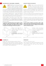
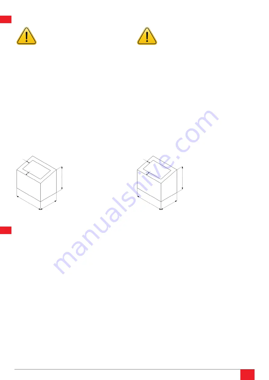
Wskazanie stref zwiększonych sił
ssawnych wiatru określa się na
podstawie podstawowych wymiarów
budynku (rys.1), gdzie:
A= L/10 lub H/5
,
B= W/10 lub H/5
(do określenia stref
wybierać mniejszą wartość oblicze-
niową).
Rys 1. Podstawowe wymiary budynku/określenie stref zwiększonej siły ssącej wiatru.
KONSERWACJA
Podczas napraw stosować tylko oryginalne części zamienne!
Stosowanie innych części zamiennych lub tańszych zamienników
może prowadzić do poważnych szkód w mieniu lub zagrożenia dla
zdrowia osób przebywających w pobliżu systemu PV! System Corab®
jest to jednorodny i spójny zespół elementów.
A
B
L
W
H
HAZARDS TO PROPERTY AND HEALTH
Caution!
Connection of the installation must be
conducted only by qualified personnel with a proper
fitter license. Corab® mounting systems can be used
only inaccordance with their original intended purpose
described in the manual that also contains information
regarding maintenance. The manufacturer shall not be liable for any
damage resulting from non-compliance with instructions of this
installation manual. The assembly must be performed in line with OH&S
and rules concerning work at heights.
In order to ensure many years of operation of the photovoltaic system, it
must not be mounted and used in areas with a high level of dustiness
(dust, sand) or environmental pollution leading to so-called acid rain.
All calculations concerning system resistance should be made in
accordance with the current standards regarding wind load for the
so-called 1st wind-load zone, in the case of which speed of wind must
not exceed 79 km/h. What is more, whenever there have been extreme,
percussive wind blows exceeding 79 km/h, the installation must be
re-inspected.
The contents of this installation manual are up-to-date as of the
delivery of the manual. The manufacturer shall reserve the right
to make changes that will not be detrimental to the technical
condition of the offered systems.
Indication of zones with increased
suction forces of the wind is determined
on the basis of general dimensions of
the building (Fig.1), where:
A= L/10 or H/5,
B= W/10 or H/5
(to determine the
zones, choose the lower calculation
value).
Fig. 1. General dimensions of the building/determination of zones with increased suction force
of wind.
MAINTENANCE
For repairs, use only original spare parts!
The use of other spare parts or cheaper third-party alternatives may lead
to serious damage to property or hazards to health of people in the
vicinity of the PV system! The Corab® system forms a uniform and
consistent set of elements.


