4
5
6
7
8
9
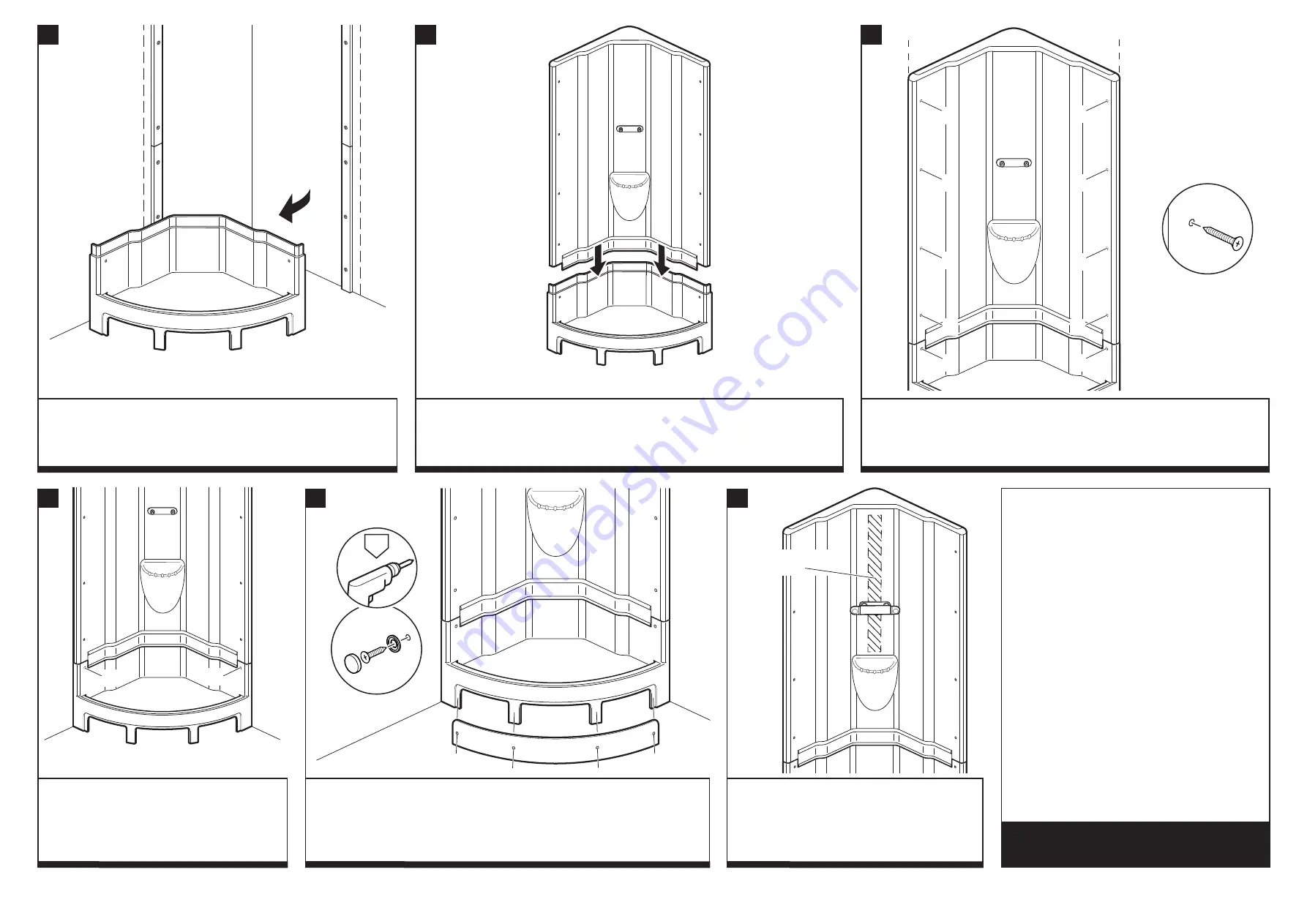
Swing the base unit out from the corner to gain enough space to access the
back.
Reposition the pod back into the corner and realign the front edges of the wall unit with the
lines marked on the walls.
IMPORTANT: Fix in position in the order shown (A, B, C, & D) using 50mm screws.
DO NOT OVERTIGHTEN.
If after fixing the wall unit, there is a misalignment
between the wall and base units, remove the two
base unit fixing screws (
X), realign the base and re-fix.
DO NOT OVERTIGHTEN.
Fit the shower valve (refer to the manufacturer’s instructions).
Through the access hole in the base unit, connect the speed fit barrier pipes to the
water inlets. Ensure the hot and cold pipes are connected to their corresponding
connections. Fit a shower waste and pipe work. Check for leaks. Position the access
cover, drill through the cover and base using a 3mm drill bit. Fix the cover using 25mm
screws, plastic washers and screw caps.
DO NOT OVERTIGHTEN.
The shower handset riser rail should only be fitted
onto the corner above the shower valve. The corner
has built-in reinforcement for the fixing screws.
SEALING: Although the unit should be watertight
without sealing, Silicone sealant can be applied along
the horizontal joints and over the screw holes.
A PRODUCT OF THE CORAM
GROUP OF COMPANIES
Coram Shower Pods Limited
Stanmore Industrial Estate
Bridgnorth
Shropshire WV15 5HP
www.coramshowerpods.co.uk
Attach the two speed fit barrier pipes to the rear connections on the back of wall unit. Check
for leaks.
Position the wall unit onto the base.
NOTE: Lowering the wall unit onto the base is a TWO person job.
Ensure the clips on the
IMPORTANT
If silicone sealant is used you must not use
or work on the base unit for 24 hours after
installation.
DO NOT use bleach, scouring powders, solvents
or other aggressive cleaning agents. To clean use
warm soapy water and a clean cloth and rinse off.
NOTE: The base should be inspected six months
after installation, check for any floor movement
and adjust the legs if necessary to ensure they are
all resting on the floor.
50mm
25mm
X
X
CUSTOMER CARELINE:
01746 713410
C
A
B
D
D
D
D
C
A
B
REINFORCEMENT
STRIP
ø 3
mm


