Hardware Manual — Product Description
In firmware version 2.07 or later, the status LEDs 5, 6, and 7 are used as alarm
indicators. The LEDs are labeled as MN, MJ, and CR (starting at LED 5). If any
points in the database with a priority of minor, major, or critical are in alarm, the
corresponding LED will be illuminated. If there are no points of that priority in
alarm, the LED will not be illuminated.
1.4.2 I/O Module Front Panel
The front panel has eight LEDs, which show the operation of the eight control
relays. Output 1 corresponds to control point 1, output 2 to control point 2, and so
on. If the LED is illuminated the associated control relay is closed.
1.5 Rear Backplane
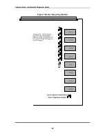
The following is an explanation of the components on the backplane (Figure 2):
•
There are four 50-Pin Amp Champ connectors labeled P1, P2, P3, and P4.
These are used for the Discrete I/O terminations.
•
If the end devices are tied to signal ground in existing installations, then the
jumpers across the pins, labeled INGND and GND should be placed in the
NULL position (vertically across the pins).
For new installations, it is preferred that the alarm common signals are attached
to signal ground on the back of the RTU. To accomplish this, the jumpers must
be placed horizontally across the INGND and GND pins.
•
There is a 34-pin ribbon cable connector labeled CHASSIS EXPANSION.
This is used to attach any additional chassis for extra I/O connections.
•
There are eight DB9 connectors labeled Port 1 through to Port 8. These are
used for connecting the TBOS Ports using RS 422/RS-485.
•
The RTU chassis and all the metal shells of connectors are internally connected
to the CHASSIS GROUND stud. When the RTU unit is installed, you should
run a cable from the CHASSIS GROUND stud to chassis ground at the site.
•
There is a 2-pin Power Terminal for the – 48 Volts and Ground connections.
The –48 Volt line should be fused at 2 Amps – slow blow.
•
The RJ11 Modem connector (labeled MODEM) and the 50-pin Amp Champ
connector (labeled AUXILIARY), and are for future use.
•
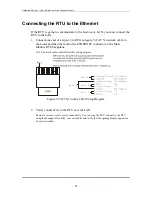
The RJ45 network connector, labeled ETHERNET is used on the Centurion II
Main Module to connect to the LAN (Local Are Network).
6


