Hardware Manual — Installation and Configuration Options
Table 7 Option A and Option B Control Relay Output Wiring for P3
Pin
Option A
Pin
Option B
1
Relay 9 Normally Closed
1
Relay 9 Normally Open
2
Relay 10 Normally Closed 2
Relay 10 Normally Open
3
Relay 11 Normally Closed
3
Relay 11 Normally Open
4
Relay 12 Normally Closed 4
Relay 12 Normally Open
5
Relay 13 Normally Closed
6
Relay 14 Normally Closed
7
Relay 15 Normally Closed
8
Relay 16 Normally Closed
26
Relay 9 Normally Open
26
Relay 13 Normally Open
27
Relay 10 Normally Open
27
Relay 14 Normally Open
28
Relay 11 Normally Open
28
Relay 15 Normally Open
29
Relay 12 Normally Open
29
Relay 16 Normally Open
30
Relay 13 Normally Open
31
Relay 14 Normally Open
32
Relay 15 Normally Open
33
Relay 16 Normally Open
34 Common
34 Common
The Relay Common, pin 34, on the I/O Amp Champ
™
connectors, P1 and P3, is
shipped with no connection to either Power Ground nor the Discrete Input
Common. This was engineered to prevent ground currents and to allow the user
to set each eight-block set of Relay Commons as they require. If desired the
Relay Common can be connected to the Discrete Input Common by installing a
jumper as shown in Figure 3 (jumper labeled P1).
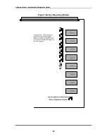
Figure 4 shows the SW2 dip switch settings which are used for the I/O module
board address based on the position of the I/O board within the RTU chassis.
14


