Hardware Manual — Installation and Configuration Options
If you already tie your input signals to ground at their source and only run one wire
back to the RTU then the two ground reference jumpers should be placed in the
vertical position.
The preferred method is to use the Power Ground on the RTU as the input common
to prevent ground loops.
2.6 Control Relay Outputs
Centurion II is shipped with form C contact wiring as described in Table 6 and
Table 7. The I/O Modules are ordered, configured and shipped with one of two
relay terminations on P1 and P3.
Option A brings out the form C contacts for each of the relays (Normally Open and
Normally Closed). Option B brings out only the Normally Open contacts. Option
B was designed to match the current wiring configuration of some of our
customers’ FibreCorp equipment and does not provide the flexibility that Option A
provides. Unless specified, the Centurion II units are shipped with Option A.
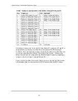
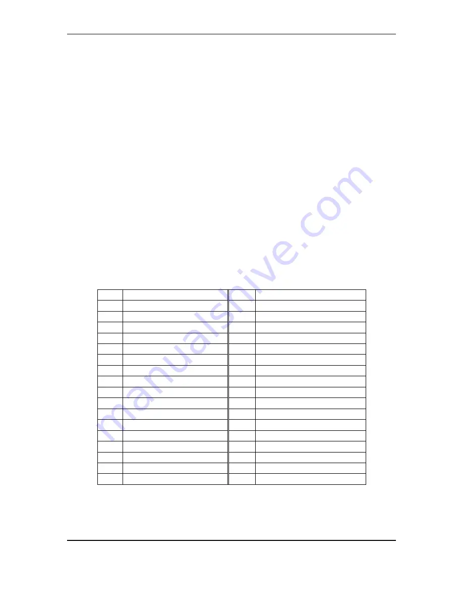
Table 6 Option A and Option B Control Relay Output Wiring for P1
Pin
Option A
Pin
Option B
1
Relay 1 Normally Closed
1
Relay 1 Normally Open
2
Relay 2 Normally Closed
2
Relay 2 Normally Open
3
Relay 3 Normally Closed
3
Relay 3 Normally Open
4
Relay 4 Normally Closed
4
Relay 4 Normally Open
5
Relay 5 Normally Closed
6
Relay 6 Normally Closed
7
Relay 7 Normally Closed
8
Relay 8 Normally Closed
26
Relay 1 Normally Open
26
Relay 5 Normally Open
27
Relay 2 Normally Open
27
Relay 6 Normally Open
28
Relay 3 Normally Open
28
Relay 7 Normally Open
29
Relay 4 Normally Open
29
Relay 8 Normally Open
30
Relay 5 Normally Open
31
Relay 6 Normally Open
32
Relay 7 Normally Open
33
Relay 8 Normally Open
34 Common
34 Common
13


