background image

Installation of MN4000 Chassis

WARNING: Working on electrical equipment 
presents significant risk and should only be 
undertaken by suitably qualified personnel 
in accordance with local applicable codes, 
standards and corresponding Personal 
Protective Equipment (PPE). This installation 
procedure assumes a panel has been safely 
removed and transported to a suitable location.

!

1

Remove the MN4000 from its packaging and place on 
a flat surface, taking care not to scratch the lens.

2

Remove the three screws securing the Camera 
Package to the Chassis.

3

Separate the Camera Package from the Chassis by 
holding the Chassis communication bulge in one hand 
and the Camera Package edge in the other hand then 
gently but firmly pull apart.

4

Place the self-adhesive drilling template provided 
into the desired location. Care should be taken to 
ensure the rear of the panel is clear of ribs or other 
obstructions prior to drilling.

5

Using the drill bit specified on the template (xxx), drill 
the three fixing holes located around the perimeter.

6

Using an appropriate holes saw or punch, drill the 
large (95mm/3¾”) centre hole.

7

Debur all rough edges and treat with rust inhibitor.

8

Align Chassis with mounting holes and attach using 
three self-tapping screws provided, making sure to 
advance the screws evenly.

9

Connect 11-30VDC to the green power connector 
(provided) and attached to Chassis. There are three 
connections.

Top:

 0V 

Centre:

 Supplemental GND* 

Bottom:

 +ve

*GND is a supplemental Ground connection. MN4000 Primary 
Ground is via the RJ45 socket and communications line. If no 
communications are installed, the Supplemental GND may 
be connected in accordance with local Electrical Codes / 
Regulatory Requirements.

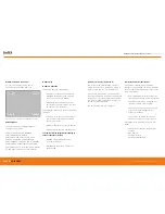
Separate

Grip here

Grip here

Chassis mounting holes

Power connections here

RUGGED 

AUTHORITY

MONITIR Series Thermal Imaging Cameras

 – User Manual

9

Document Reference MONITIRSERIESUM Rev. A

Summary of Contents for MN4000 series

Page 1: ...USER MANUAL MN4000 MN4100 SERIES THERMAL IMAGING CAMERAS RUGGED AUTHORITY www cord ex com...

Page 2: ...rmal Imager CONTENTS Introduction 8 Quick Start Guide 10 Mechanical Installation 12 Important Network Information Parameters 13 Camera web server 14 CorDEX MONITIR software 15 MODBUS HTML 15 IP Addres...

Page 3: ...r communicating with devices such as Programmable Logic Controllers PLCs The CorDEX MN4xxx may be installed in a standalone or multi camera mode with each camera incorporating a built in web server fo...

Page 4: ...settings You have now accessed the CorDEX MN4100 series camera From this screen you can setup and provide basic control commands to the camera 9 Click Submit The camera will now restart with desired...

Page 5: ...the rear of the panel is clear of ribs or other obstructions prior to drilling 5 Using the drill bit specified on the template xxx drill the three fixing holes located around the perimeter 6 Using an...

Page 6: ...mation thermal imager is intended for permanent installation into fixed locations for industrial automation control and safety monitoring purposes Installation is via an M6x4 threaded boss located on...

Page 7: ...cket and power terminals 2 Insert power and communications cables into camera via 2xM16 compression glands provided NOTE these glands will accept cables with outside diameters from 3mm 7mm 3 Connect 1...

Page 8: ...K INFORMATION AND PARAMETERS IMPORTANT NOTICE CorDEX MN4000 cameras are shipped as DHCP enabled as setup configuration is via the USB port located on the front of the camera CorDEX MN4100 cameras are...

Page 9: ...9Hz Home tab The Home tab is the default tab after logging into the camera Under the Home tab it is possible to change the image type image colourisation set rising and falling isotherms and to toggl...

Page 10: ...lling Isotherm click the OFF ON toggle switch to the ON position green and insert the alarm value in the box adjacent to the button Click Send to Camera Any temperature in the cameras Field of View FO...

Page 11: ...ier input by the installer which pinpoints the camera location once set this should not be changed unless the camera duty is altered The unit of measure can be selected from three potential options Ce...

Page 12: ...of identifying where the camera is located in a particular facility User configurable 3 Ip Address The IP Address of the camera User configurable 4 Mac Address The Mac Address of the camera Factory se...

Page 13: ...ommended initial setup mode for MN4100 cameras as they are shipped with a factory set static IP address To communicate with the camera ensure the PC running the MONITIR Application is connected to the...

Page 14: ...codes 3 6 and 16 with the addresses as defined in the following table MODBUS Function code 3 6 16 TCP Registers HTML Browser A web browser may be used to setup all aspects of the camera operation the...

Page 15: ...re cfk is at s 8 2 176 5 dhcp is at s 8 2 176 25 upper 8 bits loc is at s 8 2 176 8 next 16 characters ethIpAddress is at s 8 2 176 26 next 4 bytes ethSubnetMask is at s 8 2 176 28 next 4 bytes ethGat...

Page 16: ...mbient __packed uint16_t palette_lut PALETTE_ LARGEST __packed uint16_t palette_temp PALETTE_ LARGEST __packed lepton_settings_type settings __packed uint32_t firmware __packed uint32_t alarm_status _...

Page 17: ...on as default MN4000 ship with DHCP Enabled non static address MN4100 Ship with static IP address of 192 168 1 100 Ip Address Discovery Auto Find IP The units use the network DHCP server to assign IP...

Page 18: ...Client ReceiveTimeout 3000 listBox1 Items Clear send data MonitIR client Send RequestData RequestData Length new IPEndPoint IPAddress Broadcast 46000 then receive data while true try var ServerRespon...

Page 19: ...locally at the camera MN4100 Factory reset The MN4100 Factory Reset is achieved by pressing and holding the Factory Reset button located at the rear of the camera for one second PB 15 14 HWVersion 1 0...

Page 20: ...R YOUR PRODUCT Register your product now at http www cord ex com register your product and receive a 12 month extended warranty Terms Conditions apply www cord ex com RUGGED AUTHORITY NOTES RUGGED AUT...

Page 21: ...Copyright 2015 CorDEX Instruments Limited All other brand and product names are trademarks of CorDEX Instruments Limited Document Reference MONITIRSERIESUM Rev A...

Reviews: