background image

Page 34

AFTER EACH RIDE

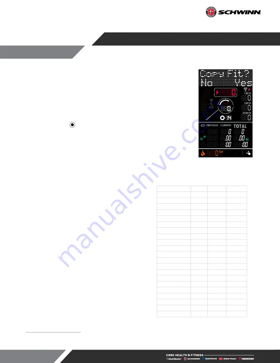
Fig. 24

 USB Retrieval

Upload data from the console to your USB drive

The ride data file is a great tool for people to track their rides and see their 
progress. After ride is complete you may save ride data from the console to a USB 
stick. 

1. 

Insert USB stick into console port.

2. 

Message center will display 

COPY FIT?

 message as in Fig. 24. 

3. 

Tap the right 

 button to begin the upload.

4. 

Console will save the ride file as 

SCHWINNZ1.CSV

4

5. 

Message center will return to SUMMARY when upload is complete.

6. 

Once the data upload is complete, the stick may be removed.

The ride data file will display the following

5

:

•  Summary data for the entire ride
•  Summary data for each stage
•  Total ride data recorded every second

RIDE SUMMARY

Total Time

32.9

Minutes

Total Distance

9.14

MI

AVG Power

98

MAX Power

210

AVG RPM

104

MAX RPM

112

AVG HR

138

MAX HR

155

CAL

226

RIDE DATA

Power

 RPM

 HR

 DISTANCE

29

90

101

0

48

89

101

0

48

89

101

0.01

48

89

101

0.01

48

89

102

0.01

48

89

101

0.02

48

89

101

0.02

48

89

101

0.02

48

89

101

0.03

Table 1

 Ride Summary Example

If a ride file exists on the USB stick with the filename SCHWINNZ1.CSV the console will save the file with the next number: SCHWINNZ2.CSV. 
The console will increment numbers as needed as long as there is space on the USB stick.

The console continues to record data aftter the ride is complete, however lines with no recorded activity are ignored in the summary calculations.

Summary of Contents for 9-7470

Page 1: ...OWNER S MANUAL CORE HEALTH FITNESS Z X BIKES CONTACT SUPPORT NOW ...

Page 2: ...33 MAINTENANCE MODE 35 CONSOLE PROCEDURES 36 TROUBLESHOOTING 38 MAINTENANCE 39 TOOLS 39 ADJUSTING THE HANDLEBAR TENSION 42 SUPPORT SERVICE 43 SUSTAINABILITY COMMUNITY Creating positive impact through thoughtful action In order to reduce our packaging s negative influence on marine life and waterways we have replaced expanded polystyrene EPS with 100 recycled corrugate which can be recycled again t...

Page 3: ...uidelines ADAAG requirements and any required local codes or regulations www access board gov ada 2 This equipment is designed for use in a commercial gymnasium or health club To ensure the proper use of the equipment in a safe manner all users of the equipment should read this manual before using the machine This machine should be made a part of your club training program in order that the equipm...

Page 4: ...long hair and keep towels away from the moving parts Face forward at all times and never attempt to turn around while the machine is moving 12 Obtain a medical exam before beginning any exercise program If at any time during exercise you feel faint dizzy or experience pain stop and consult your physician Use the value calculated or measured by the console for reference purposes only 13 DANGER Ther...

Page 5: ...ement of these stickers If you find any stickers missing or damaged the replacement numbers are shown on the support site and following pages See Support and Service to order replacements 740 9686 050 5824 050 5795 050 5735 050 5727 Serial Label 050 5724 050 5828 002 2444 050 5847 050 5823 050 5829 050 5827 050 5822 050 5821 050 5826 050 5825 Fig 2 Label Locations 9 7520 Shown IMPORTANT LABEL LOCA...

Page 6: ...SEAT POST PLACEMENT LEFT UGC 050 5823 STICKER HBAR POST PLACEMENT RIGHT UGC 050 5824 STICKER HBAR POST PLACEMENT LEFT UGC 050 5825 STICKER FORE AFT SEAT SLIDER RIGHT UGC 050 5826 STICKER FORE AFT SEAT SLIDER LEFT UGC 050 5735 LABEL DO NOT LOOSEN ZX BIKES 050 5724 LABEL PEDAL BOLT TORQUE 050 5847 LABEL WARNING MEDICAL Notice images are not to scale ...

Page 7: ...ENGLISH UGC 050 5829 LABEL WARNING FRENCH UNIVERSAL CYCLE 050 5827 STICKER FORE AFT HBAR SLIDER UGC 050 5727 LABEL BELT IDLER TORQUE TIMING 700 9686 SIDE BADGE SCHWINN 65MM 002 2444 Seal Quality Schwinn Ø30mm Notice images are not to scale ...

Page 8: ...Page 7 FORK DECALS 050 5794 9 7510 Only DECAL FORK Zs V2 050 5795 9 7520 Only DECAL FORK Za V2 050 5796 9 7480 Only DECAL FORK Xs V2 050 5797 9 7470 Only DECAL FORK Xa V2 Notice images are not to scale ...

Page 9: ...121 cm 300 lbs 136 kg PRODUCT SPECIFICATIONS Part A Console Schwinn Z Only B Handlebar C Wear Strip D Height Adjustment Pop Pin Same for Seat Post Handlebar Post E Handlebar Post F Generator Schwinn Z Only G Flywheel H Stabilizer I Transport Wheels J Resistance Knob Emergency Brake K Seat Saddle L Seat Slider M Fore Aft Cam Lever Adjustment N Leveling Foot O 4iiii Powermeter Crank P Pedal with Mor...

Page 10: ...9 SKU 9 7470 9 7480 Desc The Schwinn XA Bike The Schwinn XS Bike Fig 5 9 7470 Shown Unit Weight Width Length Height Max User Weight 130 lbs 59 kg 20 7 in 52 5 cm 42 4 in 108 cm 47 7 in 121 cm 300 lbs 136 kg ...

Page 11: ... Pin 1 Turn pop pin counterclockwise and pull to loosen 2 While having the pop pin pulled out adjust the seat or handlebar tube to desired height WARNING Do not lift the Seatpost or Handlebar posts above the STOP mark on the tube 3 Release pop pin and turn clockwise to lock Tighten pop pin until post is secure without wobble ...

Page 12: ... Seat Post adjustment Schwinn Za Shown Emergency Stop 1 Press down on the emergency stop handle Adjusting the Resistance 1 Turn handle clockwise to add resistance 2 Turn handle counter clockwise to reduce resistance ...

Page 13: ...n Adjusting the Handlebar or Seat Slider 1 Raise the slider cam lever handlebar or seat cam lever seat to adjust slider 2 Adjust slider to desired position 3 Return lever to original position to lock Ensure cam lever is secure before using the unit ...

Page 14: ...Page 13 TRANSPORT STORAGE It is recommended to apply the brake to lock the flywheel and unplug the console during transport and storage to prevent inadvertent console activation and battery drain ...

Page 15: ... At this time remove any sub components from the pallet and set aside for later assembly Once all packaging has been removed lay all parts out in a clean open area to prepare for assembly Should any component not be present or if you have any operational questions please refer to SUPPORT SERVICE After assembly a complete visual inspection and test of the features and functions of the assembled uni...

Page 16: ...SCREW M2 2 9 5 PHP TF SS 730 0900 740 9571 CAP LOWER BAR SLIDER SCREW M6X15 FHM SS SCREW M8x1 25 18mm HHC HE AS ZP SF NP Grd 10 9 110 4332 740 8145 SCREW M8X1 25 BB AXLE 718 6110 STOPPER F A HBAR ACPU 740 8607 CALIBRATION TOOL ZERO POINT ACPP Fig 9 Assembly Parts Print this page to compare ...

Page 17: ...Page 16 PROCEDURE Fig 10 1 Lift the cam lever then slide the handlebars into the handlebar post ...

Page 18: ...Page 17 110 3507 718 6110 Fig 11 2 Install the handlebar stopper into the handlebar post then use a 4mm allen key to secure it using the M6 x 15mm flat head machine screw ...

Page 19: ...Page 18 740 9571 110 4343 Fig 12 3 Use a 2 phillip screwdriver to secure the slider cap to the handlebar post using four 4 M2 2 x 9 5mm pan head screws ...

Page 20: ...Page 19 Fig 13 If assembling the X Bike Skip this Step 4 Plug the console cable into the back of the console ...

Page 21: ...Page 20 Fig 14 5 Tip the bike forward so the handlebars are resting on the ground then slide threaded foot plates and into the frame ...

Page 22: ...e 21 110 4076 120 3388 120 3385 740 8247 Fig 15 6 Use a 12mm open ended wrench to secure the rear stabilizer to the frame using two 2 of the M8 flat washers M8 split lock washers and M8 x 20mm flange bolts ...

Page 23: ... 22 110 4076 120 3388 120 3385 740 8247 Fig 16 7 Use a 12mm open ended wrench to secure the front stabilizer to the frame using two 2 of the M8 flat washers M8 split lock washers and M8 x 20mm flange bolts ...

Page 24: ...Page 23 Fig 17 8 Return the bike to standing 9 Loosen the seat slider tension lever then slide the seat assembly onto the seat post ...

Page 25: ...4 110 3682 Fig 18 10 Use a 5mm allen key to tighten the M6 x 26mm socket head cap screw located underneath the seat post to lock the seat slider assembly into place then tighten the seat slider tension lever ...

Page 26: ...al into the left crank arm then hand thread the M8 pedal bolt through the crank arm and into the pedal 12 Use a torque wrench with a 8mm allen socket to torque the pedal bolt to 37 Ft Lbs 50 Nm 13 Repeat Steps 11 12 for the right side pedal ...

Page 27: ... X Bike Skip this Step 14 Use a 2 phillips screwdriver to remove the battery cover on the powermeter and install two AA batteries 15 After installing the batteries tap any button on the console to wake it up then spin the crank arms and ensure that the console is displaying RPMs ...

Page 28: ...ust the four 4 leveling feet located on the front and rear stabilizers to level the bike and ensure it does not move or wobble during the ride NOTE If the bike is physically moved the leveling feet may need to be readjusted 17 Assembly is complete Proceed to First Time Setup on the next page ...

Page 29: ...ltaneously then tap the button to enter Maintenance Mode 2 Press the button until GEAR is shown in the message center then press the button 3 If the value in the message center reads OFF Press the button to switch to ON then press the button to save the change 4 Return to the Maintenance Mode main menu 5 Press the button until GEAR CAL is shown in the message center then press the button 6 Slide t...

Page 30: ...ut off the console to begin a new workout Description Function STAGE Button In ACTIVE mode used to start and stop the stage timer If pressed again moves stage data to PREVIOUS column from CURRENT In MAINTENANCE mode used to scroll backwards through menus or decrease a value ZONE MODE ENTER Button In ACTIVE mode used to toggle data type shown on the zone meter Changes apply only to active ride Note...

Page 31: ...on the console will alternate between Total and Active To connect Hold the watch near the icon on the console this is where the NFC reader is located When the display and watch detect each other the Bluetooth button on the display will flash and then turn solid blue and watch will ask user to confirm connection with the display Once connection is confirmed by user it will finalize and data will be...

Page 32: ...d for csv data extraction and software uploads Reset Button Located under the console Forces console to enter IDLE mode resets the computer to all preferences selected in MAINTENANCE mode Message Center The top part of the console display 2 If display turns off immediately when pedaling stops this indicates that battery is below minimum charge Adequate charge will be restored after pedaling contin...

Page 33: ...splay window will show both Active and Total Calories per Apple Watch calculations Pairing with Samsung Galaxy Watch The Z console has the capability to connect using Near Field Communication NFC with Samsung Galaxy Watch must be running software 4 8 or later and have NFC set to On 3 When a Galaxy Watch is connected the console cannot also connect to an Apple Watch or App To connect Hold the watch...

Page 34: ...efault MAX HR value is shown in the message center change in MAINTENANCE mode Press the buttons to increase or decrease value by 1 or hold to increase or decrease by 5 every 0 5 seconds Press the button to save the value shown in the message center If not pressed the console will return to ACTIVE without saving the value after 5 seconds 3 Tap the button three times to enable HR or App Pairing then...

Page 35: ...following5 Summary data for the entire ride Summary data for each stage Total ride data recorded every second RIDE SUMMARY Total Time 32 9 Minutes Total Distance 9 14 MI AVG Power 98 MAX Power 210 AVG RPM 104 MAX RPM 112 AVG HR 138 MAX HR 155 CAL 226 RIDE DATA Power RPM HR DISTANCE 29 90 101 0 48 89 101 0 48 89 101 0 01 48 89 101 0 01 48 89 102 0 01 48 89 101 0 02 48 89 101 0 02 48 89 101 0 02 48 ...

Page 36: ...Red Orange Yellow Green Blue Cyan Pink White Brightness 1 10 Blinks when setting Default 5 Open Ant On Off 3 Sec Avg On Off Calories On Off Passcode Off On7 Timeout up to 10 Minutes Zone Lock Off On8 Sensor Type 4iiii 4iiii Scan 4iiii CAL System options submenu Summary Shows Hours and SW version GEM Firmware Shows Firmware version System Reset Pressing the button resets console to factory default ...

Page 37: ...e button until 4iiii SCAN is shown in the message center then press the button to begin the pairing process 3 Check the side of the power sensor for a 4 or 5 digit ANT ID1 code then spin the crank to activate it for pairing 4 The message center will show available ANT devices within range Press the button to change devices When the matching crank ANT ID code appears in the message center press the...

Page 38: ... button to complete the calibration CAL COMPLETE will show in the message center 9 The GEAR option can now be turned back to ON in Maintenance Mode CALIBRATING POWER2 Console comes pre paired with the powermeter out of the box Directions for updating the software in the crank are on the support site 4iiii app required for crank firmware updates 1 Tap the and buttons simultaneously then tap the but...

Page 39: ... not plugged in damaged Troubleshoot the angle sensor assembly including wiring NO PM 4iiii Cal Crank not paired with console or battery in crank low Pair crank to console check or replace crank battery CAL FAIL 4iiii Cal Left crank not at 6 o clock during calibration or bike was touched during calibration Recalibrate NOTHING FOUND 4iiii Scan Console cannot find a compatible ANT device within rang...

Page 40: ...ols listed available when performing maintenance Tool Metric Allen Key Set Screwdriver Set Phillips Metric Open Ended Wrench Set Screwdriver Set Flat Large Adjustable Crescent Wrench Torque Wrench Metric Socket Set Snap Ring Pliers Multi meter USB Flash Drive Loctite 680 zip ties various sizes IMPORTANT NOTE Do not use power tools on fasteners it will damage the plastic shrouds MAINTENANCE ...

Page 41: ...feet X Clean and seal frame4 X Lubricate horizontal and vertical seat sliders5 X Lubricate pop pins6 X Inspect welds for any signs of cracking X 1 Wipe console with a soft non abrasive cloth to remove all sweat after each use Use a soft non abrasive cloth and mild spray cleanser to clean the console Never use abrasive cleaning liquids cleaning liquids with an oil base ammonia or alcohol 2 Using a ...

Page 42: ...llow any cleaning product Protect surrounding area clothing from ex posure Use in a well ventilated area Follow all product manufacturer s warnings CORE Health and Fitness cannot be held responsible for damage or injuries resulting from the use or misuse of cleaning products Preventive Maintenance Cautions While maintaining equipment you will want to avoid spraying any liquids directly onto any su...

Page 43: ...32 inset 3 If a torque wrench is not available please skip to step 6 4 Close the fore aft adjustment lever then use a torque wrench with a 10mm deep socket to tighten the fore aft lever adjustment nut to 2 2 5 Nm 1 5 Ft Lbs 5 This will conclude the procedure Fig 28 Fig 29 If Torque Wrench is not available 6 With the fore aft adjustment lever up tighten the adjustment lever nut 1 4 of a turn then c...

Page 44: ...rts Orders or any Customer Service needs please contact us by phone email or through our 24 hour support site PHONE EMAIL SUPPORT AVAILABLE MONDAY FRIDAY 6AM 5PM PST 4400 NE 77th Avenue Suite 250 Vancouver WA 98662 Tel 360 326 4090 800 503 1221 support corehandf com Warranty information https corehandf com warranty To request access scan or visit CONNECT COREHANDF COM General Inquiries Warranty Re...

Page 45: ...ved Star Trac the Star Trac logo and StairMaster are registered trademarks of Core Health Fitness LLC Schwinn and Nautilus are registered trademarks of Nautilus Inc used under license to Core Health Fitness LLC Throwdown is a registered trademark of Throwdown Industries LLC ...

Reviews: