background image

Page 1

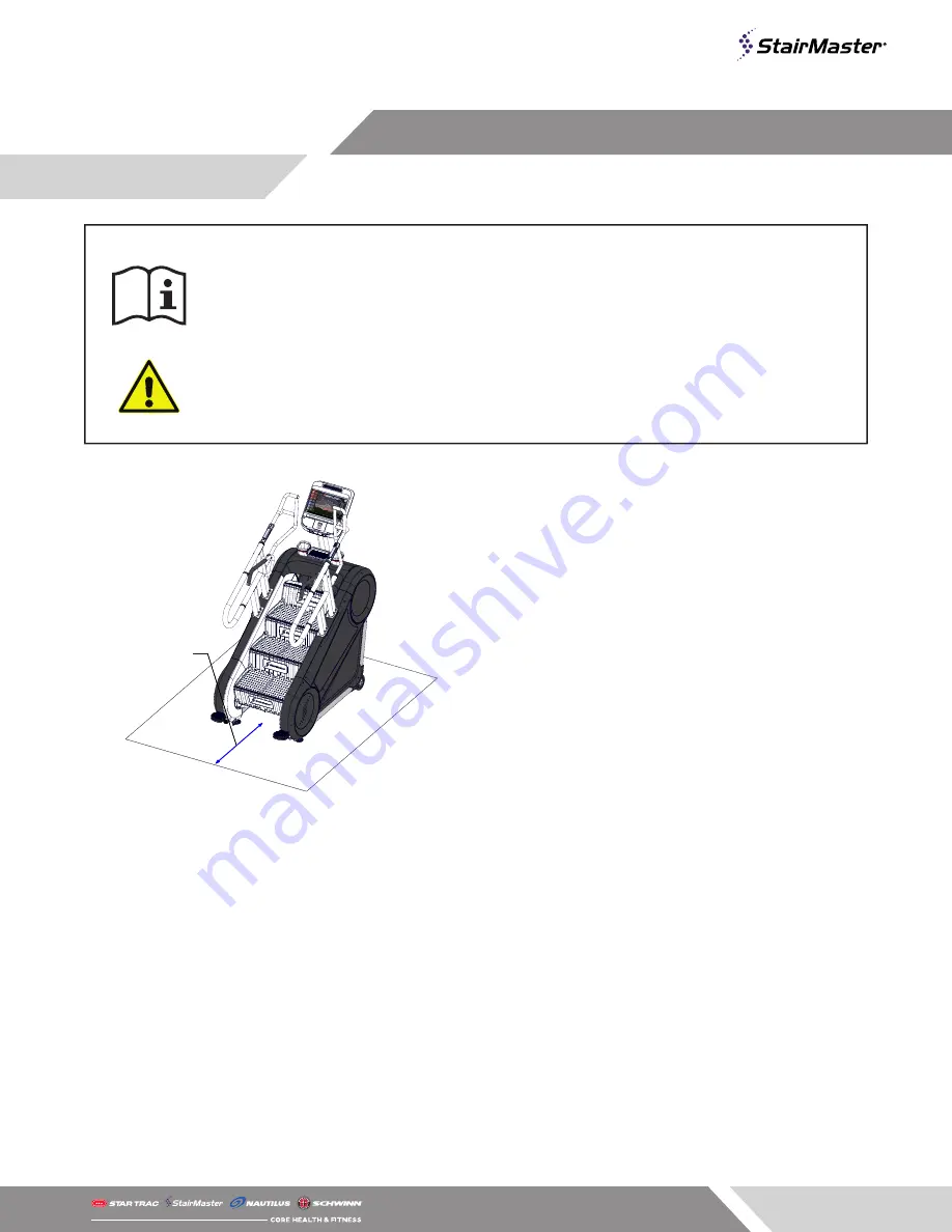
24 in (0.6 m)

24 in (0.6 m)

F

IG

. 1

- Required Clearance

1. 

Assemble and operate the machine on a solid 
level surface. Position the machine with a 
minimum of 20 inches (0.5 meters) of clearance 
on each side to allow for ease of mounting and 
dismounting. Allow for recommended minimum 
of 48 inches (1.25 meters) of clearance in front 
and behind the machine. 

The actual area for access and passage shall be 
the responsibility of the facility and should take 
into account this training envelope, Americans 
with Disabilities Act Accessibility Guidelines 
(ADAAG) requirements and any required local 
codes or regulations (www.access-board.gov/
ada).

2. 

Do not exceed the maximum allowable weight 
limit of 400 lbs. / 181 kg.

3. 

This equipment it is not suitable for therapeutic 
use.

4. 

Use care when getting on or off  the machine. 
Always use the handrails. Do not step off  of the 
machine while it is moving. Press the STOP button 
and wait for the machine to come to a complete 
stop before dismounting.

5. 

If the power supply cord is damaged, it must be 
replaced by the manufacturer, its service agent, 
or similarly qualifi ed persons in order to avoid 
hazard.

6. 

The safety and integrity of this machine can only 
be maintained when the equipment is regularly 
examined for damage and wear and repaired. 
It is the sole responsibility of the owner of this 
equipment to ensure that regular maintenance 
is performed. Worn or damaged parts must be 
replaced immediately or the equipment removed 
from service until the repair is made.

7. 

Caution: unit is heavy and requires two people for 
assembly.

8. 

After assembly, a complete visual inspection, 
and test of the features and functions of the 
assembled unit must be made prior to use.

9. 

For complete instructions refer to the owner’s 
manual.

IMPORTANT SAFETY INSTRUCTIONS

Before using this product, it is essential to read the ENTIRE Owner’s Manual and ALL installation 
instructions. The Owner’s Manual describes equipment setup and instructs members on how to use 
correctly and safely.

Read all warnings posted on the machine.

Health related injuries may result from incorrect or excessive use of exercise equipment. STAIRMASTER 
strongly recommends you to encourage your members to discuss their health program or fi tness 
regimen with a health care professional, especially if you or they have not exercised for several years, 
are over 35, or have known health conditions.

WARNING!

Summary of Contents for Stairmaster 10G

Page 1: ...10G Core Health Fitness INSTALL MANUAL ...

Page 2: ...ified persons in order to avoid hazard 6 The safety and integrity of this machine can only be maintained when the equipment is regularly examined for damage and wear and repaired It is the sole responsibility of the owner of this equipment to ensure that regular maintenance is performed Worn or damaged parts must be replaced immediately or the equipment removed from service until the repair is mad...

Page 3: ...Page 2 SKU 9 5285 Desc 10G Overall Weight Width Length Height User Weight 646 lbs 293 kg 34 9 in 88 6 cm 69 5 in 176 cm 82 3 in 209 cm 80 400 lbs 36 181 kgs PRODUCT SPOTLIGHT ...

Page 4: ... G A E I H F J D C B D G A E I H F J PART PART PART A Console E Leveling Foot I UP DOWN Keypad B Shrouds Housing F Handrail J STOP Keypad C Main Frame G Stair D Transport Wheel H Heart Rate Grips PART IDENTIFICATION ...

Page 5: ...om pallet located on the sides of the stepmill DO NOT REMOVE THE BLOCKS IN FRONT OF THE WHEELS DO NOT REMOVE 4 With the help of another person carefully turn the rear of the unit clockwise so that the leveling feet are on the ground and the two transport wheels are on the pallet Required Tools 12 Ratchet Wrench 19mm or 3 4 Socket 19mm Open Ended Wrench 9 16 Open Ended Wrench Dead Blow Mallet Knife...

Page 6: ...the pin 8 Use a 12 ratchet wrench with a 19mm or 3 4 socket and attach the wrench to the exposed nut on the inner left shroud near the bottom step 9 Turn the wrench counter clockwise to deploy the mobility wheel CAUTION The mobility wheel is not to be used outdoors and should be only used when moving the unit over short distances for cleaning or service Do not step on the machine with the mobility...

Page 7: ...0G is in its final install location use a 12 ratchet wrench with a 19mm or 3 4 socket to retract the wheel back into the frame 13 Reinstall the safety pin into the wheel up position the first small hole 14 Use a 9 16 open ended wrench to level the left and right leveling feet 15 Once the machine is level us the 19mm 3 4 open ended wrench to tighten the nut against the frame 16 Refer to the documen...

Page 8: ...nnect Get help with your general inquiries warranty registration preventative maintenance service requests and parts orders You can also make seamless service requests get real time updates manage your assets and intuitively order parts for all brands direct from the site support corehandf com Contact Information CORE HEALTH FITNESS 4400 NE 77th Avenue Suite 300 Vancouver WA 98662 Telephone 888 67...

Page 9: ... 2019 CORE HEALTH FITNESS LLC PART NUMBER 620 8763 REV A ...

Reviews: