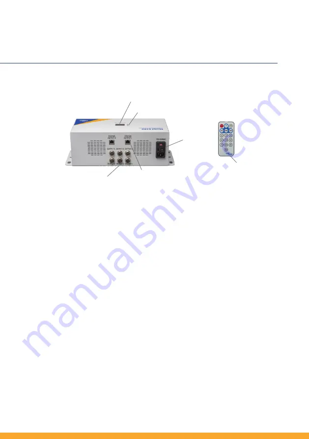
C. Description of Model 6380 Controller
12
Copyright by CORE INSIGHT, INC.
This user manual contents may change without pre-notification.
7 Setup and Operation
D. Installation
① Power: Cord input, on/off switch and input fuse selector
② LED: 4 digit display. Setting output parameter values and alarm.
③ Normal and Alarm LED: Indication for normal operation (Green) and Red for
alarm
status.
④ Circular Metal Connector (CMC): Communication terminal to emitters or
junction box.
⑤ Output Status: RS-485 link to external FMS systems. RJ-45 Ethernet cable.
⑥ Model 5711R Remote Controller
Stainless steel brackets and other mounting methods are determine by
user. Determine locations of ceiling emitters, controller and then
junction boxes at technical limitation between emitters. Recommended
primary communication cable (20 AWG) length is 10 meters from
controller to the first junction box or ceiling emitter. Maximum 15
meters is possible for small group of ceiling emitter operation. Recom-
mended RJ-11 communication cable (24 AWG) from junction box to
ceiling emitter or between ceiling emitters are 5 meters and maximum
overall length are 50 meters for 10 units of ceiling emitters.
②
③
④
①
⑤
⑥


