background image

English

Ice cream freezer

12

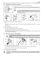
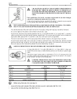
In case of failure and/or malfunctioning of the device - and every time you notice damages, mainly at the supply cable or at
the safety devices - turn off the power supply. Contact qualified and certified personnel for assistance.

NEVER operate the machine in DRY conditions or with an amount of mixture other than the one recom-
mended.

NOT RESPECTING THESE RULES, IN ADDITION TO VOIDING ANY FORM OF WARRANTY, CAN SERI-
OUSLY COMPROMISE THE SAFETY, PERFORMANCES AND  FUNCTIONING OF THE SAME DEVICE.

6.2

Commands and indicators

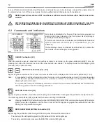
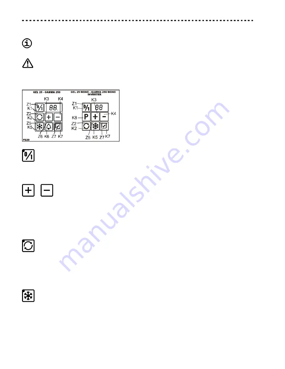
All controls and indicators for the use of the device are grouped in a
single control panel placed on the front panel. Its functioning is
low-voltage electronically managed.

I

In this manual, the buttons and indicators are identified with the relative
symbol, and/or with an imprint ([K…] for pushbuttons, [Z…] for
indicators).

The functioning of every command is described hereby: to obtain the
best results, an acknowledgment is suggested.

ON/OFF Pushbutton [K1]

When the electric supply is connected, the machine is ready to be turned on, the green indicator light [Z1] is on. By
pressing the button, the device turns on and the other buttons are enabled. The display shows the total whipping time
previously set (in prime minutes).

SETTING Pushbuttons [K3] - [K4]

By pressing these commands, the number of minutes visualised on the display will be increased or decreased (1…99).

Note:

It is suggested to set the whipping time when the device is idle, generally between 8 and 12 minutes depending
on the kind and quantity of the mixture. It is possible to increase or decrease the timing even during the
whipping for particular needs.

In any case the timer will automatically memorise, as total time, the minutes VISUALISED ON THE DISPLAY
after having pressed one of the setting pushbuttons.

BEATING Pushbutton [K2]

By pressing the pushbutton, the rotation of the beater goes CLOCKWISE. Press again the pushbutton to stop the beater.

The relative lighted indicator [Z2], signals that the beater is rotating CLOCKWISE.

Note:

Pressing the BEATING Pushbutton when the REFRIGERATION/WHIPPING command is activated ([Z5] indicator
lighted) stops the refrigeration, and the timer is put in PAUSE. By pressing again the pushbutton to start the
beating, the refrigeration starts again.

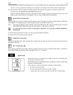
REFRIGERATION/WHIPPING Pushbutton [K5]

By pressing the pushbutton (after having set the timer) what follows will be commanded:

-

The start up of the refrigerating plant (the [Z5] indicator of this button lights up);

-

The beating, automatically, clockwise (the BEATING indicator [Z2] lights up)

Summary of Contents for GAMMA 250 MONO

Page 1: ...Z15 036 0102 V01 ING GEL OPERATING INSTRUCTIONS GAMMA GAMMA GAMMA GAMMA GAMMA 250 250 250 250 250 GAMMA GAMMA GAMMA GAMMA GAMMA 250 250 250 250 250 MONO MONO MONO MONO MONO Ice cream freezer...

Page 2: ...English Ice cream freezer 2...

Page 3: ...ICES 5 2 1 Lid s magnetic sensor 5 2 2 Extraction door s grill 5 3 TECHNICALDATA 6 3 1 Technical data plate and CE marking 6 3 2 Acoustic pressure level 6 4 CARRYINGAND UNPACKING 6 4 1 Transportation...

Page 4: ...ess to the device s moving parts beater cylinder or extracting door Any modifying of the electrical supply must be exclusively performed by professionally qualified and certified person nel Any use of...

Page 5: ...illed semicircle 5 on the bottom of the magneto 1 must coincide with the grooves 4 marked by a white line down the side and the stencilled semicircle 6 on top of the magnetic contact 2 The device will...

Page 6: ...ical Data section This data has been measured at 1 meter from the surface of the machine and at 1 60 meters from ground level during the machine s functioning 4 CARRYING AND UNPACKING Note We suggest...

Page 7: ...ALPARTS OF THE DEVICE Remove both the lateral panels unscrewing the relevant fixing screws 21 Find and unscrew the bolts 22 which fix the machine s frame at the packing s basement The outlet of the su...

Page 8: ...ording to the model extraction door 14 Also check that the following items are included spare part kit 11 tube brush 12 and ice cream blade 13 basin support 10 knobs 16 the lever 8 and the extraction...

Page 9: ...electrical socket must prevent through appropriate mechanical measures the plug s wrong connection the electrical socket must have above or annexed a breaker conformed to the in force safety laws with...

Page 10: ...rubber holder The unions are placed on the back panel of the device they are marked by a plate H2 O 20 and are labelled with IN INLET of fresh water in the device OUT OUTLET of water used by the devi...

Page 11: ...t beater s shaft turns CLOCKWISE as shown in the picture In this case the device is correctly connected and ready to be used Note do not unnecessarily start the refrigerator If the rotation is COUNTER...

Page 12: ...enabled The display shows the total whipping time previously set in prime minutes SETTING Pushbuttons K3 K4 By pressing these commands the number of minutes visualised on the display will be increased...

Page 13: ...WHIPPING Pushbutton K5 before commanding the extraction To avoid excessive stress before commanding the extraction it is necessary to OPEN THE EXTRAC TION DOOR The Z7 indicator signals that the beater...

Page 14: ...er mixtures Before operating beater ALWAYS check that beater s fixing knob 7 is FIRMLY TIGHTENED and the gasket is intact and clear of any fat Should the knob accidentally come loose and fall into the...

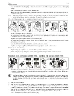
Page 15: ...g simple washing par 7 1 if you soon proceed with the production of other ice cream disassembling of parts par 7 2 and accurate washing par 7 3 if the production has come to an end MODELS GEL 25 MONO...

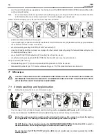
Page 16: ...on door Carry out an accurate cleaning simple washing par 7 1 if you soon proceed with the production of other ice cream disassembling of parts par 7 2 and accurate washing par 7 3 if the production h...

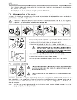
Page 17: ...TERNALSIDEEDGES ITISRECOMMENDED TOUSE SUIT ABLE PROTECTIVE GLOVES AND TOHANDLE THE BEATER ONLY BY HOLDINGTHECENTRAL HUBAND NOTTHEBLADES remove the basin support 10 by unscrewing the hand screws 16 uns...

Page 18: ...will be subsequently adjusted Carefully place beater into the cylinder taking care to keep it vertical without dropping it The slot on the beater s hub 27 goes into the shaft clutch 28 FIRMLY tighten...

Page 19: ...by the manufacturer To correctly replace the gaskets it is necessary to remove the old gaskets by using a sharp tool possibly non metallic paying attention not to scratch the seating of the gaskets t...

Page 20: ...in rooms with a temperature lower to 0 C it is INDISPENSABLE to get rid of the water in the condensator and in the inlet and outlet pipes Call the Assistance Service 10 MALFUNCTIONS WE RECOMMEND YOU T...

Page 21: ...Note it may be necessary to wait up to 30 minutes for the thermal protections to cool down With the Main Breaker on 1 the ON OFF indicator light Z1 TURNS ON but the device does not work Cause Break do...

Page 22: ...ssistance Service Unusual noises The noisiness comes mainly from the cylinder when the beating is activated Cause Beater s blades are not correctly adjusted Proceed as describes in Par 7 5 Adjusting b...

Page 23: ...English Operating instructions 23...

Page 24: ...Servizio Assistenza Technical Service Service d Assistance Kundendienst Servicio Asistencia Servicedienst COSTRUTTORE MANUFACTURER CONSTRUCTEUR HERSTELLER CONSTRUCTOR FABRIKANT...

Reviews: