UT
Handbook for Use and Maitenance – 50000 WB-80-87-95
Edition
01/11
Revisione
00
11
50000WB_e111_E.doc
1.3.3 - PRESSURE-READING OUTLETS ON 50000 WB
The machine has been equipped with 3 pressure reading outlets.
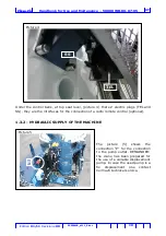
1. On the left side. On the 2 way valve, picture 6 (red colour); Pressure outlet “P”
(pressure gauge 1)
2. On the right side. On the outriggers control bank, picture 7 (Yellow colour);
pressure outlet “S” (pressure gauge 2).
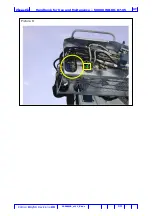
3. On the control board, picture 8 (yellow colour); pressure outlet at the function
that is operated at the time (pressure gauge 3).
1.3.4 - SETTING OF THE VARIABLE DISPLACEMENT PUMP
1. Set the flow controller differential pressure of the pump at 17 bar (247 psi) The
setting procedure needs 2 pressure gauges with maximal pressure scale at 40
bar ( 580 psi). One pressure gauge shall be installed at the position “1” , the
other one at position “2”. Lower the lever (4) of the two (2) way valve (2 way
valve for crane/outriggers , position 4 picture 6) so that the oil is sent to the
outriggers control bank. Set the flow controller of the pump in such a way that
the difference between the two pressure read at the two pressure gauges, is
equal to 17 bar (247 psi). No one lever of any function shall be moved during
the mentioned operation. The use of some function could cause the explosion of
the pressure gauges.
2. Rise the lever of the two (2) way valve (crane / outriggers) with the oil flow in
direction of the crane. , install the pressure gauge, with maximal scale at 40 bar
(580 psi) at position “3” (yellow pressure outlet on the control station). The
read pressure, with all levers in neutral position, shall be less than 30 bar (435
psi) setting the pressure at an higher level is causing a malfunctioning of the
load limiting device.
3. Set the pump cut-off valve at 280 bar ( 3982 psi), this setting is achieved by
using the valve on the pump and than slowly screw the regulator until the
pressure value read on the pressure gauge “3” on the control board To the Top
seat (yellow colour) when the jib is risen up to end stroke it reaches 280 bar
(about).
1.3.5 - READING OF THE WORKING PRESSURES
The working pressures of the crane must be taken form the pressure outlet “3”
(yellow colour) located on the control station.

