


Manuale/Manual/Manuel/Handbuch/Manual
–
07/2014
Pagina
41
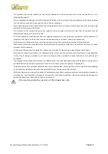
Picture
F13.12
4.
Move
the
rim
4
‐
5
cm
from
the
tool
taking
care
that
it
does
not
unhook
from
the
bead.
5.
Move
the
hook
tool
towards
the
outside
until
the
red
reference
dot
is
by
the
outside
edge
of
the
rim.
6.
Take
the
mobile
control
unit
to
work
position
B.
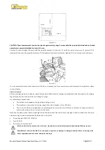
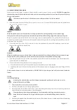
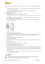
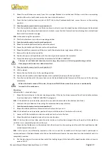
7.
Insert
lever
(A,
picture
F13.12)
between
rim
and
bead
at
the
right
of
the
tool.
8.
Press
down
on
the
lever
and
lower
the
wheel
to
bring
the
edge
of
the
rim
about
5
cm
from
the
hooked
tool.
9.
Turn
the
wheel
anticlockwise
pressing
down
on
lever
until
the
bead
is
completely
off.
10.
Move
the
toll
carrier
arm
to
its
non
‐
working
position
and
then
move
it
to
the
inside
plane
of
the
wheel.
11.
Take
the
mobile
control
unit
to
work
position
D.
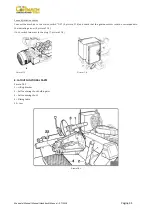
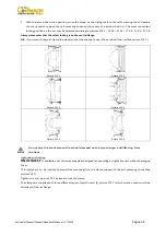
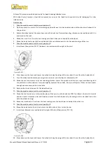
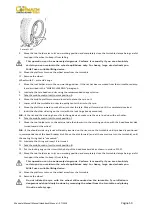
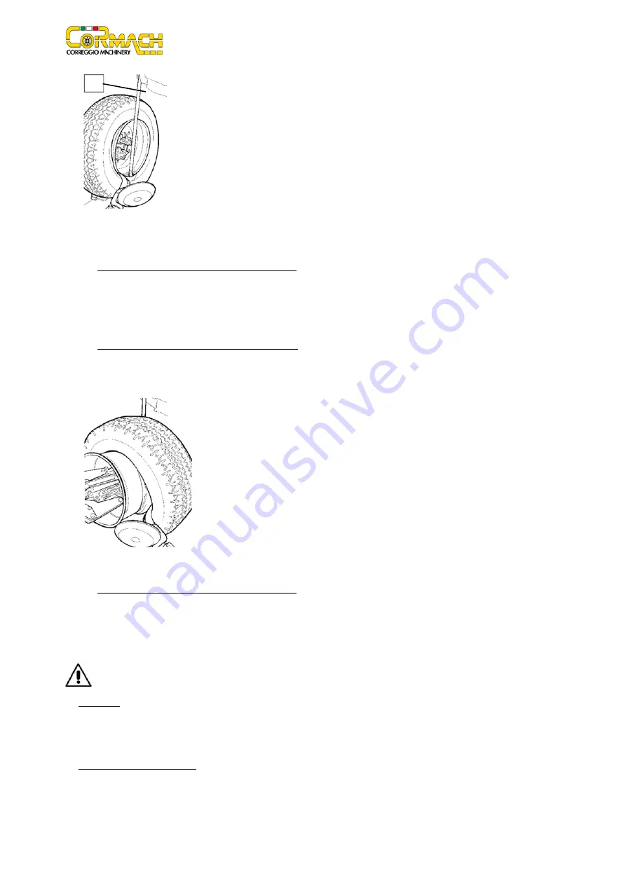
12.
Turn
the
hook
tool
180°,
insert
it
between
rim
and
bead
(See
picture
F13.13).
Move
it
until
the
bead
is
by
the
edge
of
the
rim
(best
to
do
this
with
the
wheel
turning).
Picture
F13.13
13.
Move
the
rim
about
4
‐
5
cm
from
the
tool
making
sure
the
hook
does
not
deattach
from
the
rim.
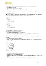
14.
Take
the
mobile
control
unit
to
work
position
B.
15.
Move
the
hook
tool
so
that
its
red
reference
dot
is
about
3
cm
inside
the
rim.
16.
Insert
lever
(A,
picture
F13.12)
between
rim
and
bead
at
the
right
of
the
tool.
17.
Press
down
on
the
lever
and
lower
the
wheel
to
bring
the
edge
of
the
rim
about
5
cm
from
the
hooked
tool.
Turn
the
wheel
anticlockwise
pressing
down
on
lever
until
the
tyre
comes
completely
off
the
rim.
When
the
bead
come
off
the
rim,
the
tyre
will
fall.
Check
to
make
sure
there
are
no
by
standers
in
the
work
area.
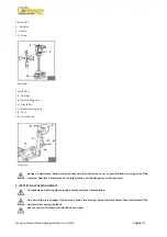
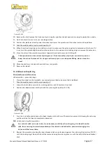
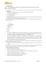
Mounting
Tubeless
tyres
can
be
mounted
using
either
the
bead
‐
breaker
disk
or
the
hook
tool.
If
the
tyre
is
not
problematic,
use
the
bead
loosener
disk.
If
the
tyre
is
very
rigid,
the
hook
tool
must
be
used.
Tyre
mounting
with
the
disk
Follow
these
steps:
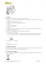
1.
If
the
rim
has
been
removed
from
the
spindle,
put
it
back
on
the
spindle
as
described
in
the
section
on
“CLAMPING
THE
WHEEL”.
A
Summary of Contents for FT 26S
Page 2: ......
Page 6: ......
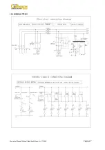
Page 33: ...Manuale Manual Manuel Handbuch Manual 07 2014 Pagina 27 19 SCHEMA ELETTRICO...
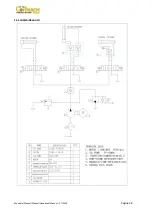
Page 34: ...Manuale Manual Manuel Handbuch Manual 07 2014 Pagina 28 20 SCHEMA IDRAULICO...
Page 35: ...Manuale Manual Manuel Handbuch Manual 07 2014 Pagina 29...
Page 61: ...Manuale Manual Manuel Handbuch Manual 07 2014 Pagina 55 19 ELECTRICAL DIAGRAM...
Page 62: ...Manuale Manual Manuel Handbuch Manual 07 2014 Pagina 56 20 HYDRAULIC DIAGRAM...
Page 63: ...Manuale Manual Manuel Handbuch Manual 07 2014 Pagina 57...
Page 89: ...Manuale Manual Manuel Handbuch Manual 07 2014 Pagina 83 19 SCHEMA ELECTRIQUE...
Page 90: ...Manuale Manual Manuel Handbuch Manual 07 2014 Pagina 84 20 SCHEMA HYDRAULIQUE...


