


Manuale/Manual/Manuel/Handbuch/Manual
–
07/2014
Pagina
61
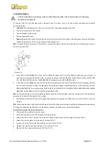
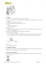
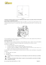
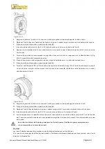
Figure
F7.1
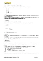
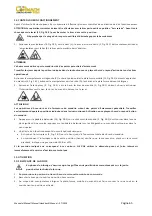
ATTENTION:
Ces
dimensions
indiquent
aussi
la
zone
opérationnelle
du
démonte
‐
pneus.
L’accès
dans
cette
zone
doit
être
interdit
à
toute
personne
non
expressément
autorisée.
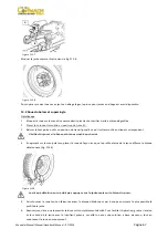
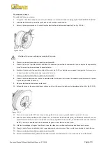
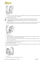
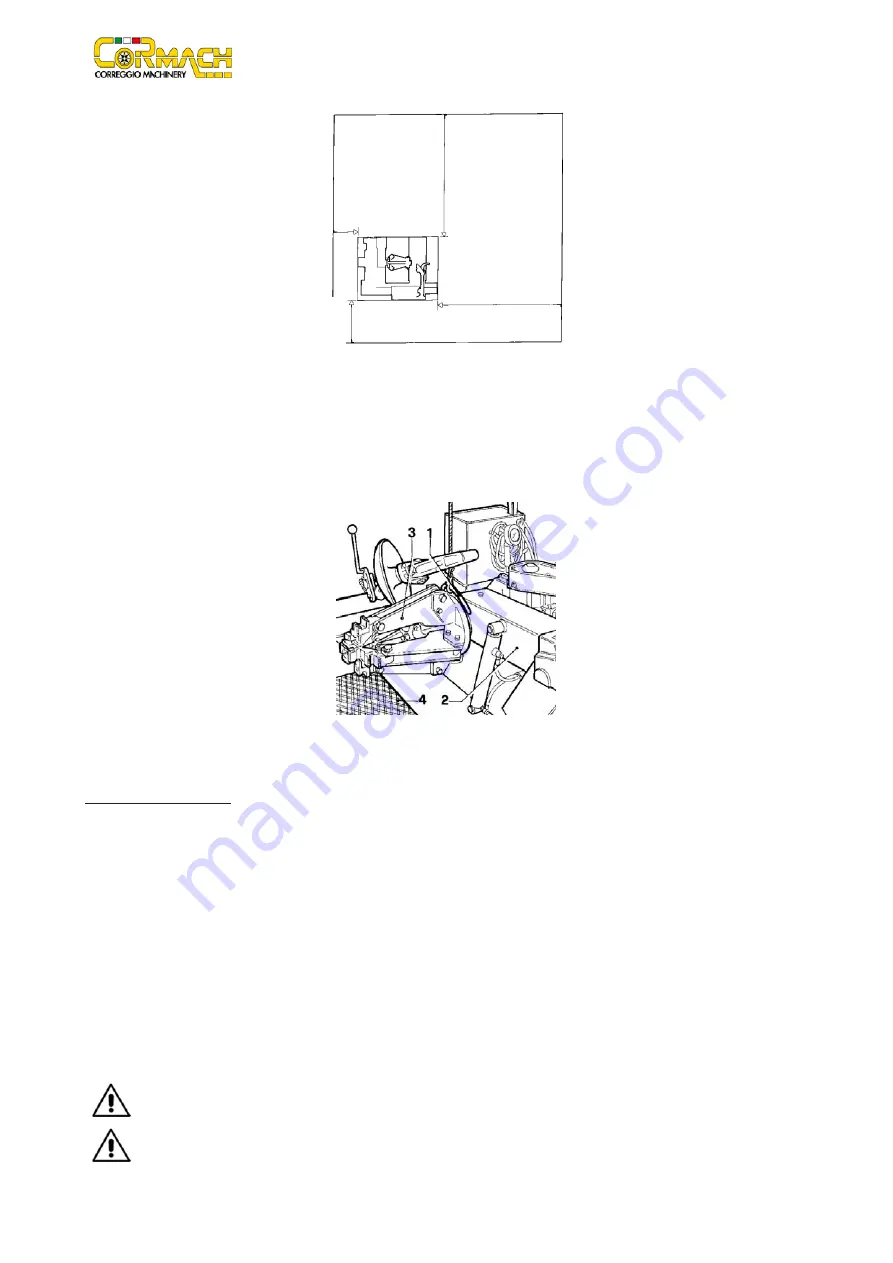
Mettre
le
démonte
‐
pneus
en
place
en
utilisant
l’anneau
de
levage
(1,
fig.
F7.2),
le
bras
porte
‐
mandrin
doit
être
complètement
abaissé
(2,
fig.
F7.2),
le
mandrin
fermé
(3,
fig.
F7.2),
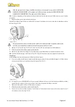
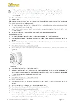
le
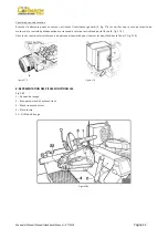
chariot
porte
‐
outils
(4,
fig.
F7.3)
en
fin
du
course,
près
du
bras.
Figure
F7.2
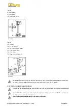
Il
n’est
pas
nécessaire
d’ancrer
la
machine
au
sol
qui
doit
simplement
n’avoir
aucunes
aspérités
pour
permettre
aux
rouleaux
de
la
plateforme
de
glisser
facilement.
Raccordement
electrique
Avant
d’effectuer
tout
raccordement
électrique
controlez
attentivement
que
la
tension
du
réseau
d’alimentation
correspond
à
celle
indiquée
sur
la
plaquette
de
voltage
(placée
à
proximité
de
la
fiche
du
démonte
‐
pneus).
Il
est
absolument
obligatoire
que:
Le
circuit
soit
équipé
d’un
bon
réseau
de
mise
à
la
terre.
La
machine
soit
reliée
à
un
disjoncteur
d’alimentation
(différentiel)
calibré
à
30
mA.
La
prise
de
courant
soit
protégée
de
manière
adéquate
contre
les
surtensions
par
des
fusibles
ou
un
disjoncteur
automatique
(Voir
les
valeurs
nominales
dans
le
tableu).
Lire
l’absorption
requise
sur
le
plaquette
placée
sur
le
démonte
‐
pneus,
et
vérifier
si
le
réseau
électrique
est
d’une
grandeur
suffissante.
Alimentation:
380V
‐
3Ph.
‐
50/60Hz
Fusible:
20A
AM
Interrupteur:
20A
Les
interventions
sur
le
circuit
électrique,
même
de
faible
importance,
doivent
être
réalisées
par
un
technicien
qualifié.
Tout
dommage
découlant
de
l’inobservation
de
ces
règles
ne
sera
pas
imputable
au
constructeur
et
entraînera
l’expiration
de
la
garantie.
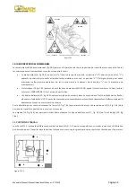
2500
mm
2500
mm
600
mm
1000
mm
Summary of Contents for FT 26S
Page 2: ......
Page 6: ......
Page 33: ...Manuale Manual Manuel Handbuch Manual 07 2014 Pagina 27 19 SCHEMA ELETTRICO...
Page 34: ...Manuale Manual Manuel Handbuch Manual 07 2014 Pagina 28 20 SCHEMA IDRAULICO...
Page 35: ...Manuale Manual Manuel Handbuch Manual 07 2014 Pagina 29...
Page 61: ...Manuale Manual Manuel Handbuch Manual 07 2014 Pagina 55 19 ELECTRICAL DIAGRAM...
Page 62: ...Manuale Manual Manuel Handbuch Manual 07 2014 Pagina 56 20 HYDRAULIC DIAGRAM...
Page 63: ...Manuale Manual Manuel Handbuch Manual 07 2014 Pagina 57...
Page 89: ...Manuale Manual Manuel Handbuch Manual 07 2014 Pagina 83 19 SCHEMA ELECTRIQUE...
Page 90: ...Manuale Manual Manuel Handbuch Manual 07 2014 Pagina 84 20 SCHEMA HYDRAULIQUE...


