20
Technical service manual
GEO 10
It is possible to update the measuring sensor program (FIRMWARE) by means of a service
program, without the need to open the measuring sensor itself. For measuring sensor pro-
gramming, see “Utility Programs”.
Measuring sensor sound indications
Upon power-on, each head beeps a given number of times. The number of beeps is
used as a code to identify each head as follows:
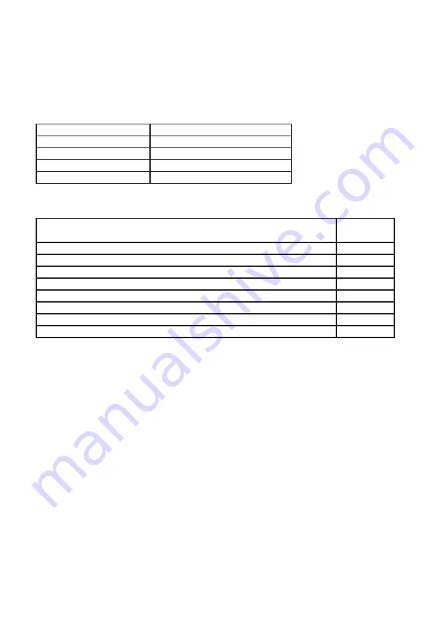
Head
Number of beeps
Front left
Nessun beep
Front right
1 beep
Rear right
2 beeps
Rear left
3 beeps
Afterwards, if there are any problems with the sensors, the head will give a longer
beep and then the following additional beeps:
Problem
Number of
beeps
Full scale of longitudinal goniometer not calibrated
1 beep
Full scale of transverse goniometer not calibrated
2 beeps
Full scales of both goniometers not calibrated
3 beeps
Full scale of inclinometer not calibrated
4 beeps
Full scale of inclinometer and longitudinal goniometer not calibrated
5 beeps
Full scale of inclinometer and transverse goniometer not calibrated
6 beeps
Full scale of inclinometer and both goniometers not calibrated
7 beeps
Thermal characterization of inclinometer missing
8 beeps
If goniometer calibration is missing (head will beep 1-2-3-5-6-7 times), switch off the
head and replace the uncalibrated goniometer(s).
If the head gives 8 or more beeps, switch off the head and replace the inclinometer.
Switch the head back on again and count the beeps.
If you get 4 beeps, calibrate the full scale of measuring sensors, and this will enable
goniometer zero and inclinometer full scale calibration.
BATTERIES
Each head is powered by four 1.2V-2600 mA/h NiMh AA penlight batteries.
Open the lower panel (Fig. 10) and insert the 4 batteries observing the polarity shown
in the battery holder.
After inserting the batteries, close the lower panel.
WARNING: USE ONLY RECHARGEABLE 1.2V-2600 mA/h NiMh AA BATTERIES.
BATTERIES-RECHARGING PROCESS
Battery charging is started by connecting the head charging cable to the electrical
panel (A, Fig. 1); the charging process is indicated by the GREEN LED on the head
connector lighting up. The manufacturer cannot be held responsible for any damage
caused by the use of batteries other than those specified at paragraph “BATTERIES”.
Summary of Contents for GEO 10
Page 1: ...WHEEL ALIGNER GEO 10 03 2014 SERVICE MANUAL UK...
Page 2: ......
Page 36: ...36 Technical service manual GEO 10 1 2...
Page 37: ...Technical service manual GEO 10 37 4 3...
Page 38: ...38 Technical service manual GEO 10 5 6...
Page 39: ...Technical service manual GEO 10 39 7 8...
Page 40: ...40 Technical service manual GEO 10 9 10...
Page 41: ...Technical service manual GEO 10 41 19...
Page 42: ...42 Technical service manual GEO 10 20 21...
Page 43: ...Note 43...


