Use and Maintenance Manual – 09/2016 Rel. 0
Page 21
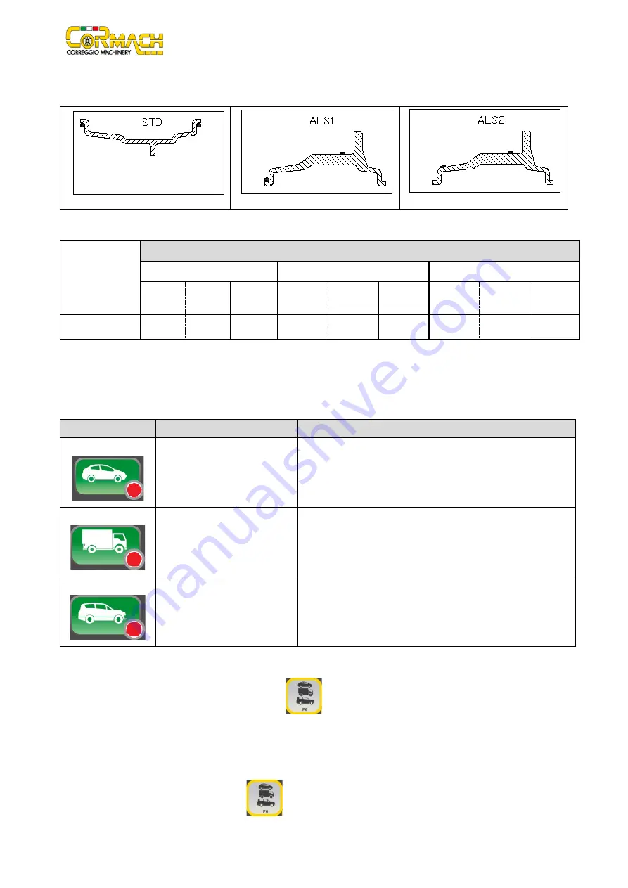
The position of the balancing weights along the section of the rim in the various Program Types is shown in picture F15.1.
Figure F15.1: Position of the weights in the various Program Types along the section of the rim
Angular position of the balancing weights in the several Program Type is shown in table T15.2.
Table T15.2: Angular position of the balancing weights in the various Program Types
Machine data
acquisition
system
Program Type
STD
ALS1
ALS2
Internal
plane
External
plane
Static
plane
Internal
plane
External
plane
Static
plane
Internal
plane
External
plane
Static
plane
Manuale
H12
H12
H12
H12
H6
H6
H6
H6
H6
In table T15.2 while the symbol “H6” indicates that the angular position of the weight is at 6 o’clock.
15.2 Wheel types
The machine allows choosing between three different Wheel Types as listed in table T15.3.
Table T15.3: Wheel Types to select
Wheel Type
Vehicle
Notes
CAR
Auto-vehicles
TRUCK
Truck
Default power on
SUV
Off-Road vehicles
Not suitable for balancing truck wheels
Each of the above programs set up specific values to measure the wheel dimensions and to calculate the imbalances. The special
features of each program are listed in the following paragraphs.
To select a specific Wheel Type, press repeatedly [P6] key
until the corresponding LED turns on as shown in table T15.3.
15.2.1 CAR wheel type (auto-vehicles)
The selection of the CAR Wheel Type allows the balancing of wheels of auto-vehicles. For OFF-ROAD vehicles, it may be appropriate
to select the SUV Wheel Type (see paragraph below).
To select CAR wheel type, press repeatedly [P6]
until the CAR LED of the Wheel Type group LED lights up. See table T15.3.
Summary of Contents for MEC 200 TRUCK
Page 1: ...WHEEL BALANCERS MEC 200 TRUCK MEC 200 C TRUCK USE AND MAINTENANCE MANUAL UK...
Page 2: ......
Page 4: ......
Page 43: ......


