IDC Pro 255 Service Manual
Publication Number: 621058649SER
- 8 -
© 2016, Cornelius Inc.
M
ULTI
-
FLAVOR
V
ALVE
C
ONFIGURATION
!
WARNING:
Disconnect power to the unit before accessing the MFV valve.
Table 2.
Step
Action
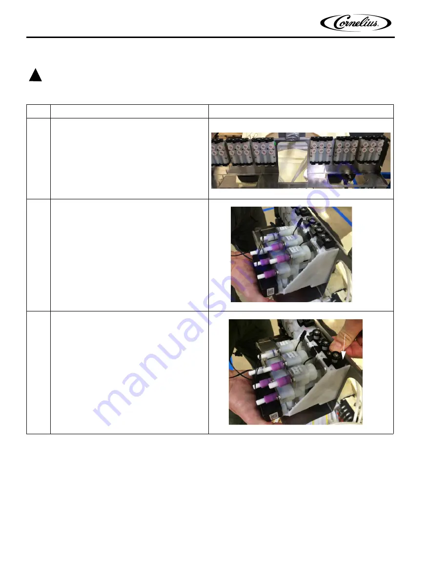
1
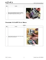
Back-block layout behind each valve bank.
Figure 4.
2
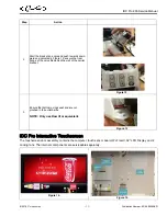
MFV Valve Module placed on the back-block.
Figure 5.
3
Press the top snap (Dovetail) of black-block
towards down as indicated in Figure 6.
Figure 6.


