Cornell Communications, Inc
4800 Installation Manual 07-31-18
13
System Wiring Terminations
The 4800 Digital Emergency Communication System utilizes (3) types of connection cables as shown in the
system riser.
•
Pair #16 AWG, stranded, non-shielded cable, from the PS to the Control Panels/Switches.
•
Pair #22 AWG, stranded, non-shielded cable, circulating from the PS to all of the Power Detect (J9)
connections on the Control Panels. (Two outer terminals)
•
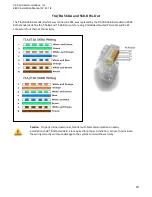
Cat5e cable, Standard straight-thru, TIA/EIA 568A or TIA/EIA 568B, from the Control Panels/Switches, to
the Call Station(s) and to the maintenance room for the phone line, as shown in the riser on the previous
page.
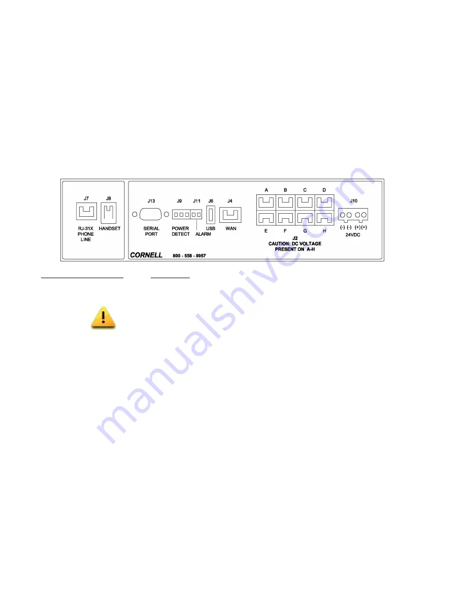
The label below is provided on the Control Panel(s). The Expansion Switch uses a modified circuit board and
label that does not have the J7 or J8 ports.
Connection Port
Description
J2
8 available RJ45 ports to connect to Remote Control Panels/Remote/Switches or Call
Stations. (Standard straight-thru, TIA/EIA 568A or TIA/EIA 568B. See page 18)
Caution: Do not connect a PC to these ports. The ports have DC voltage to power the
Call Stations. Connecting to any of these ports will damage the PC!!
J4
WAN port used to connect additional Remote Control Panels and Expansion Switches.
(Standard straight-thru, TIA/EIA 568A or TIA/EIA 568B)
J6
USB programming port. A pre-programmed USB drive must remain installed for
the Call Station message and/or Fault message options to work.
J7
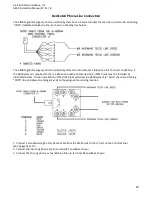
Analog “POTS” dedicated telephone line or RJ-31X Jack connection, for “POTS” line
sharing. (Standard straight- thru, TIA/EIA 568A Telecom Cat5e)
J8
Handset connection. (Available on the Main or Remote Control Panel)
J9
Power Detect/AC failure. A pair of wires connects to the power supplies AC/Battery fail
circuits. The (2) outside terminals on the J9 connector are used.
J10
24VDC power supply connections.
J11
Normally Open (N.O.) contact provided for remote alarm connection. The J11 port is
not active on the ES’s. Example: Cornell part # D-113P, D-113CH
J13
RS232 serial programming port.
Summary of Contents for 4800 series
Page 5: ...Cornell Communications Inc 4800 Installation Manual 07 31 18 5 4800 System Components ...
Page 12: ...Cornell Communications Inc 4800 Installation Manual 07 31 18 12 4800 System Riser ...
Page 18: ...Cornell Communications Inc 4800 Installation Manual 07 31 18 18 Power Supply Fault Detect ...


