Cornell Communications, Inc
4800 Installation Manual 07-31-18
14
System Wiring Terminations Cont.
The 4800 System is shipped from the factory fully programmed, with the local site information that was
provided by a Cornell Communications dealer. Identify each of the system components and install them in their
required locations. Use the System Wiring Terminations page to assist with the following connections.
•
Connect the Call Station(s) RJ45 port to the Control Panel(s) and Expansion Switch(s), (A-H) J2 port, using
Cat5e cable and EMI filter.
(EMI filter detail on page 17).
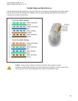
(Standard straight- thru, T1A/E1A 568A or T1A/E1A 568B, See page 19)
•
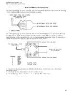
Connect a 22 AWG pair of wire, from the Power Supply(s) AC/BAT Fail terminal blocks, to the (2)
outer terminals, on the J9 connector at the Control Panel(s).
(See page 18).
•
If the system uses multiple Control Panels and Expansion Switches, connect a Cat5e cable from
any (4800M) Main Control Panel (A-H) J2 port, to the (4800R) Remote Control Panel, WAN (J4)
port. Additional Control Panel(s) can be connected to expand the system by following the same
procedure.
o
Connect a Cat5e cable from the (A-H) J2 port of the existing Control Panel(s), to the
WAN (J4) port of the Add-On Control Panel or Expansion Switch. This will provide an
additional (8) Call Station connections. (Subtract (1) J2 port if expanding further).
Note: Additional Control Panel(s) and Expansion Switches can be added on to
any available (A-H) J2 port, on any of the Control Panel or Expansion Switch in
the system.
(WAN ports do not require EMI filters)
•
With the AC power disconnected to the Power Supply(s), connect a 16 gauge power pair, from the
Power Supplies DC (+) (-) terminals, to the J10 plug of all the Control Panel(s) and Expansion Switch(s).
(See Page 17 for connection details).
o
The B-5248A has (7) set’s of PTC protected DC outputs that can provide power for up to a
combination of (7) Control Panel(s) and Expansion Switches. Install EMI filters as required. (See
page 17)
o
Larger systems will require multiple power supplies. Refer to the system riser for details.
Contact Cornell Communications Technical Support Staff with any questions or concerns prior to applying
power to the system!!!
1-800-558-8957
Summary of Contents for 4800 series
Page 5: ...Cornell Communications Inc 4800 Installation Manual 07 31 18 5 4800 System Components ...
Page 12: ...Cornell Communications Inc 4800 Installation Manual 07 31 18 12 4800 System Riser ...
Page 18: ...Cornell Communications Inc 4800 Installation Manual 07 31 18 18 Power Supply Fault Detect ...


