Page 3
SRP 003-304 • Issue 9 • July 2004
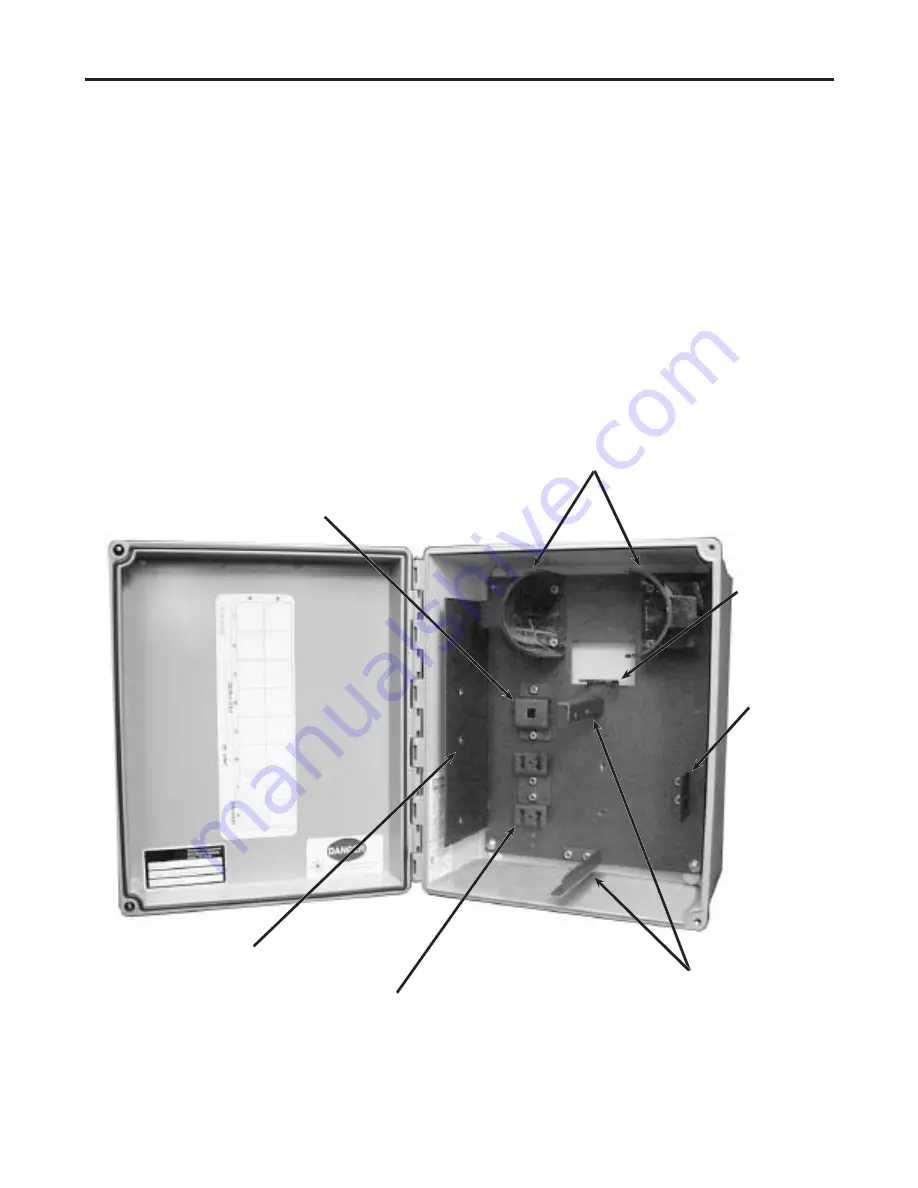
Connector
Panel
Support
Brackets
Sheath Retention Bracket
Central Member Strain-Relief Bracket
Splice Tray Mounting Location
Fan-out
Bracket
Drop Cable
Strain-Relief
Bracket
Radius Control Guides
4.
Tools and Materials
In addition to the usual complement of
installation tools, the following are required for
this installation:
•
Slotted and Philips-head screwdrivers
•
Tape measure
•
Pliers
•
8-mm (
5
/
16
-inch) open or box wrench
•
Utility pole or wall mounting hardware (as
required by your installation)
•
Two cable entry port fittings (ordered
separately) and sealant (if required)
5.
Components
5.1
Components are illustrated in Figure 2.
The base plate is the dark metal plate that holds
the components inside the enclosure. It is
secured by four screws.
5.2
An installation kit is provided that
includes cable ties, central member strain-relief
hardware, a sheath retention kit and a quick-
release latch kit.
6.
Unpacking Stubbed Units
Stubbed unit unpacking instructions are
detailed in SRP 003-310. This instruction is
provided with stubbed hardware shipping
containers.
Figure 2


