Page 11
SRP-003-545 • Issue 4 • July 2004
12.3
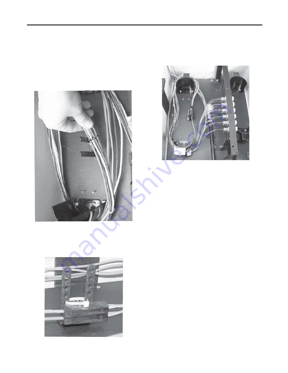
Route the buffer tubes around the radius
guides three times in a counterclockwise
direction. Mark the location of the fan-out
bracket on the buffer tubes as shown in
Figure 23 to determine the length required.
12.4
Install fan-out assemblies and connectors
according to the instructions provided with the
BTF kits.
12.5
Route the buffer tubes around the radius
guides and secure the fan-out assemblies to the
fan-out bracket as shown using a cable tie
(Figure 24).
Figure 23
Figure 24
Figure 25
12.6
Route the connectorized fan-out tubing
around the guides and plug connectors into the
connector panel (Figure 25). Refer to the
previous connector care caution to avoid
damaging the connectors during installation.
12.7
Label the connector end of the pigtail
with its port identifier. Record information
appropriately on the record label inside the
front door (Figure 18).
IMPORTANT:
Accurate record keeping is
imperative for an organized installation.
NOTE:
The splice tray holder and its mounting
bracket should be reinstalled to allow future splicing
capabilities.
13. Installing Drop Cable
13.1
The EDC is designed to accept up to six
drop cables. Feed 3 meters (10 feet) of drop
cable through the fitting you installed on the
right at the base of the closure.
1) Route three complete loops of the subunit
around the radius guides (Figure 28).
2) Match the subunits to the corresponding
panels and simulate how they will lie.
3) Mark the length on the subunit and trim the
cable to this length.
13.2
Gently secure cable with no central
members to the bracket using cable ties.


