Standard Recommended Procedure 003-794-AEN | Issue 14 | March 2020 | Page 15 of 27
Step 4:
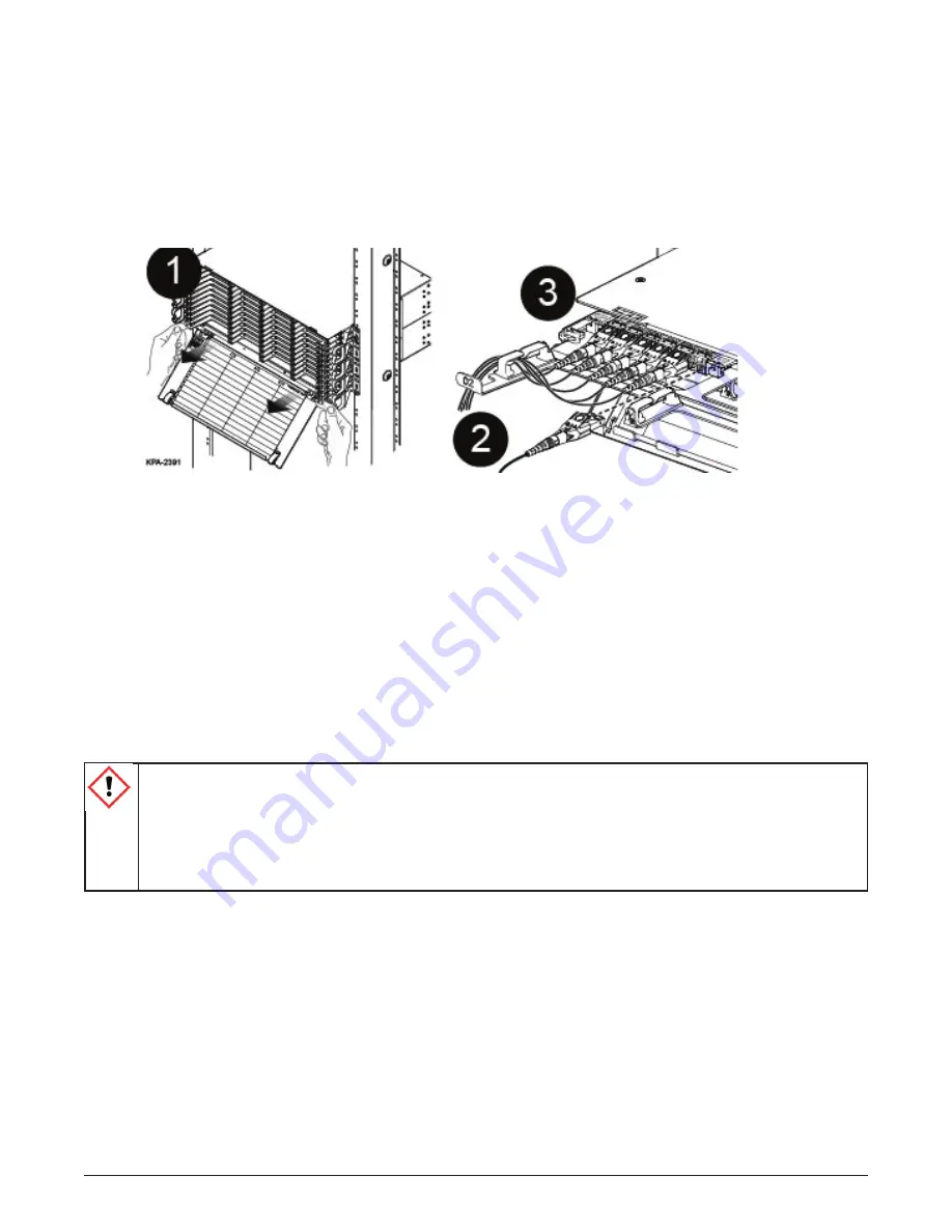
Route jumper legs, right and/or left out either side of the housing. (Do NOT cross legs in opposite
directions.) Store legs in clips at front of tray (Figure 20, step 3).
NOTE:
Inspect the jumpers during the routing process to ensure no kinking occurred. If a kink has occurred, re-
route the jumper leg to remove the kink.
Step 5:
Route the jumper legs per your installation plan to their final destinations.
Step 6:
Repeat for remaining jumpers.
Figure 20 — Mate Jumpers and Route Legs
4.8
Install MTP
®
Adapter Panels
The MTP adapter panel comes in configurations to support both single-mode (SM) and multimode (MM)
applications. Adapters have been clearly labeled identifying port (1, 2, 3, etc.). Each tray within the housing will
support a maximum of four MTP panels.
Adapter panels may be installed from the front or back of the EDGE™ housing. During the initial installation,
it is recommended to install all panels and all trunk cables into the panels from the rear of the housing. Install
panels and trunk cables tray by tray, starting with Tray 1, slot A. Additional panels and trunks should be installed
with the same recommendations always working from right to left and bottom to top as seen from the rear of
the housing.
CAUTION:
Previously installed panels that were not fully populated during the initial installation and
have a harness, jumper, or trunk connected on the front side of the MTP adapter panel will require
slack from the front in order to be removed from the rear of the housing and install additional trunks.
Installer MUST obtain slack in the fiber connected to the panels on the front side. Without slack,
tension in the jumpers will result in pulling on fiber legs with potentially disrupted service, specifically
if disconnect is required.


