STANDARD RECOMMENDED PROCEDURE 003-139-AEN | ISSUE 1 | JANUARy 2017 | PAGE 10 OF 13
9.3.
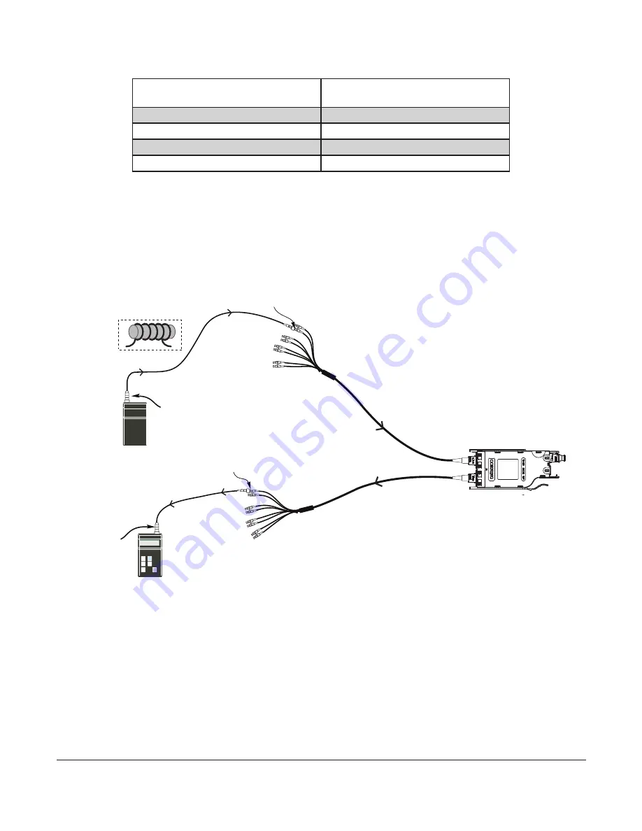
Table 4 provides a complete guide to the test sequence with a light source and test harness at
the front-mounted TAP MTP connector and a meter and test harness at the front-mounted TAP MTP
connector of the system shown in Figure 14.
Source LC Position at LIVE port test
harness “A”
Meter # 1 and TAP port test
harness at LC #
A-2
1
A-4
3
A-6
5
A-8
7
Table 4:
Test Sequence
9.4
To begin testing the TAP portion of the MTP Tap module from the “A” LIVE Port harness to the
module TAP port test harness (Figure 14):
Step 1:
Install the
Light Source/RJ1
LC connector adapter
onto the LC number 2
connector of a test harness plugged into the LIVE port of the MTP Tap module.
Step 2:
Install
RJ2’s LC connector adapter
onto the LC number 1 connector of a harness
plugged into the TAP port of the MTP Tap module.
Figure 14
EDGE8 Tap Module “A”
“A”
HPA-1004-EDGE8
LIVE
port test harness
TAP
port test harness
Light
Source
Do NOT
disconnect
multimode only
LC #8
LC #8
LC #2
LC #1
M1
Do NOT
disconnect
0.00 dB
RJ2
and
adapter
RJ1
and
adapter


