I ns t al l at i o n C MA - XX X- A E N
P a ge 3 3
Draft
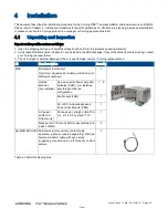
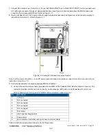
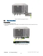
Figure
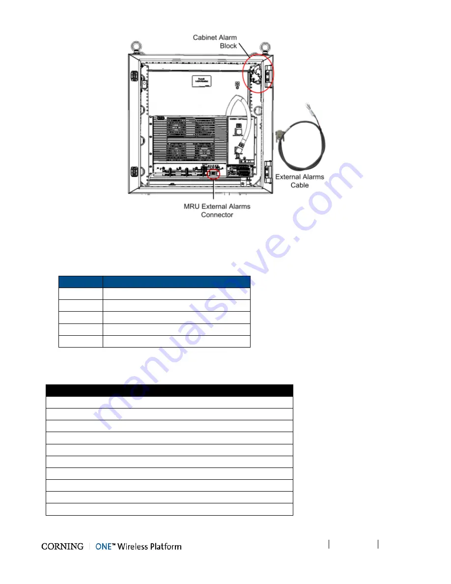
4-12. Location of External Alarms Connector and Cabinet Alarms Block
B. Route the cable alarm wires to the alarm block, located on the upper right corner of the cabinet.
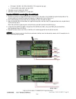
C. Connect the external alarm connections to the cabinet according to the following:
Refer to Table
4-6 for External Alarms cable wiring description.
Color
Description
Red
+48 V_COMMON
Green
-48 V_EXIST INDICATION
Brown
-48 V_DOOR ALARM
Black
-48 V_HEX ALARM
White
-48 V_FUTURE ALARM
Table
4-6. External Alarms Cable Wiring Description
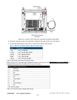
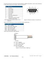
Refer to Table
4-7 for wiring description of MRU External Alarms connector and to Error! Reference source not found. for
examples of the upper and lower bock cabinet wiring connections.
External Alarms Connector Pin No.
1
Common
6
Door Alarm
2
NC
7
HEX Alarm
3
NC
8
Future Alarm
4
NC
9
Exist Indication
5
NC
NC =Not Connected
Table
4-7. External Alarms to Cabinet Block Wiring

