
Installation Manual | CMA-794-AEN | Page 14
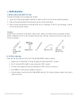
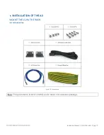
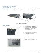
MOUNT THE A2 ON THE WALL
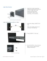
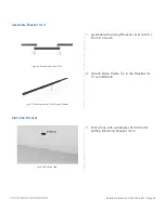
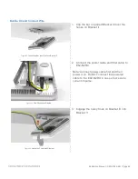
Attach Handle to A2
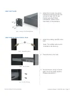
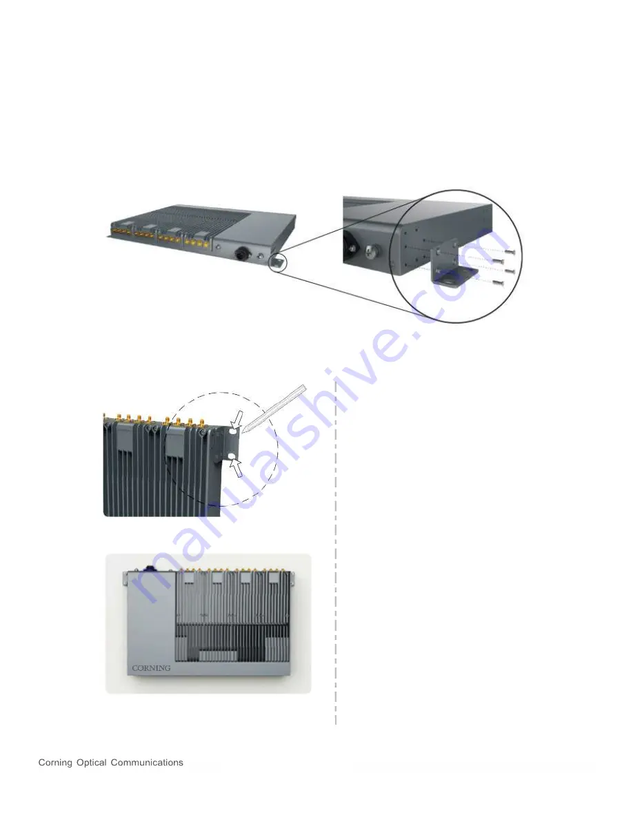
Attach the 19-inch mounting brackets to the rear of the A2 unit, using 4 screws M3×16 per bracket
and the Phillips screwdriver. Observe the orientation of the brackets shown in Figure 17.
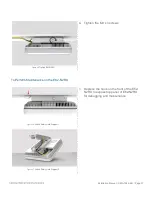
Figure 17.
Attaching a 19-in Mounting Bracket
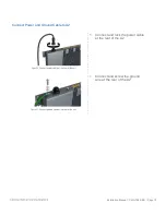
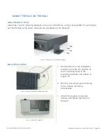
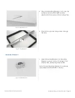
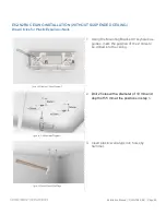
Mount A2 to Wall
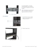
Figure 18.
Marking the position of mounting holes
1. Hold the A2 to the installation
location and mark the position of
the 4 mounting holes in the
mounting brackets.
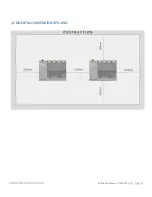
2. Drill the mounting holes according
to the chosen mounting
accessories.
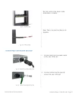
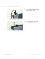
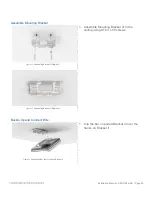
Figure 19.
Mounting completed
3. Attach the dowels, expansion
screws, and fasten the A2 to the
wall.


