


STANDARD RECOMMENDED PROCEDURE 003-333 | ISSUE 9 |
March
2012 | PAGE 3 OF 6
3.5. Lifting precautions
CAution:
The Optical Splice Enclosure weighs over
50 pounds. Two people are required to move or lift it into
position.
4.
mountinG
The enclosure ships with the mounting brackets attached in the location shown to mount the enclosure:
•
on the wall,
•
onto T-slot rails
•
or into a 23-inch utility rack with frontal projection.
4.1. Wall-mounting
importAnt:
Make sure there is adequate space above
and below the unit to route cables. Do not
violate the minimum bend radius for any
cable being installed. If you are installing a
pass-through kit, maintain between 0.8 to
2 inches between the two units.
step 1:
choose a dry, vertical surface on
which to mount the cabinet. The type
of hardware used is dependent on
the mounting location; wall anchors
may be required for adequate support
on sheetrock walls. Wall-mounting
hardware is not provided.
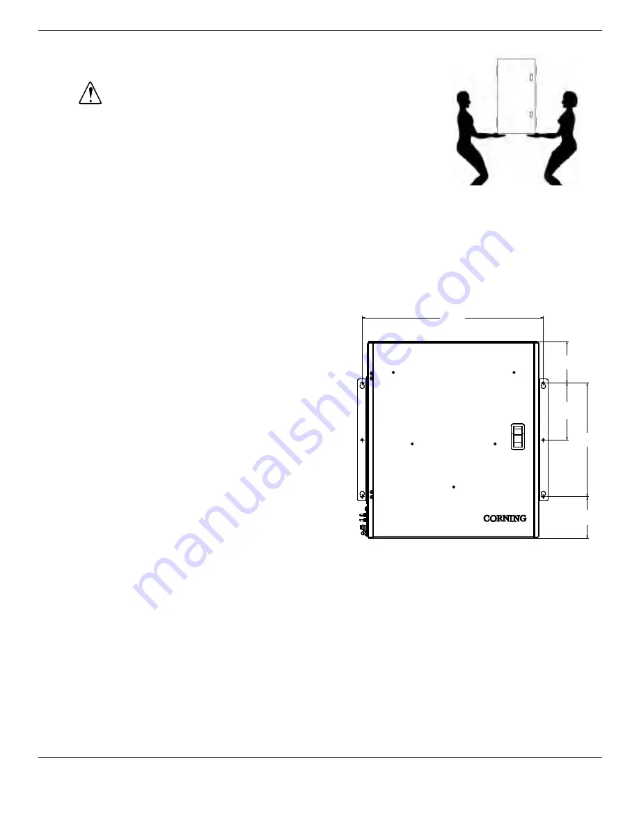
step 2:
Using the mounting template provided,
mark the locations for the six mounting
screws.
step 3:
Leaving a 1/8-inch gap behind the
screw head, install the two top mounting screws in the wall using the distances shown.
step 4:
hang the unit on the two screws through the upper holes in the mounting brackets. Tighten
the screws against the brackets.
step 5:
Install the remaining screws in the lower holes in the brackets and tighten securely.
4.2. t-slot mounting
T-slot rack mounting kits are purchased separately. refer to the accessories section of this instruction
for part number information. Follow the instructions provided with the kit.
22.32
5.11
7.00
14.00
5.11
TPA-4082


