


STANDARD RECOMMENDED PROCEDURE 003-333 | ISSUE 9 |
March
2012 | PAGE 6 OF 6
Corning Cable Systems LLC • PO Box 489 • Hickory, NC 28603-0489 USA
1-800-743-2671 • FAX +1-828-325-5060 • Interna1-828-901-5000 • http://www.corning.com/cablesystems
Corning Cable Systems reserves the right to improve, enhance, and modify the features and specifications of Corning Cable Systems’ products without prior notification. All
trademarks are the properties of their respective owners. Corning Cable Systems is ISO 9001 certified.
© 2012 corning cable Systems. all rights reserved. Published in Mexico.
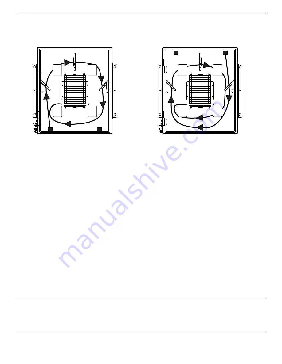
step 2:
route at least one full loop of buffer tubes in a clockwise direction around the radius guides,
through the routing clips, and into the splice trays as shown. Note that the cable can enter
from the top or bottom of the cabinet. Do not bend cable too sharply.
note:
Use cable ties every 10-12 inches to bundle buffer tubes. Do not overtighten cable ties.
step 3:
Mark buffer tubes where they will enter the splice tray.
8.
spLiCinG
step 1:
Bring splice tray and fiber to splice tray shelf.
step 2:
Strip buffer tubes at the mark made in Section 7.
step 3:
Secure buffer tubes to splice trays. Splice fibers as explained in the instructions provided
with the try and for the splicing method you are using.
step 4:
Once splicing is complete, load the splice tray into the stacker, beginning at the bottom.
step 5:
Secure all trays using the provided hook-and-loop strap.
note:
a Slotted core ribbon kit (purchased separately) is required for installation of slotted core ribbon
cable. Refer to Section 2 for part number information. Follow the instructions provided with the kit.
step 6:
Confirm cable does not violate minimum bend radius before securing exterior door.
Bottom Entry
Top Entry
TPA-4087


