Corning Restricted
C o r n in g O pt ic a l Com m un ic at io ns
Us e r Man u al I C MA - 4 82 - A E N I P a g e 5 3
4.4.2
Connect the Cables
Route the
ground
,
RF
,
fiber
and
power
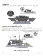
cables located previously, between the standoff mount bracket and the RAU5x
towards the interface connectors.
Note: for each cable connection, two figures are shown: one indicating a configuration without RxU67, and the other showing
a greenfield installation WITH Rxu67.
Connect the cables as follows.
•
•
•
•
•
4.4.2.1
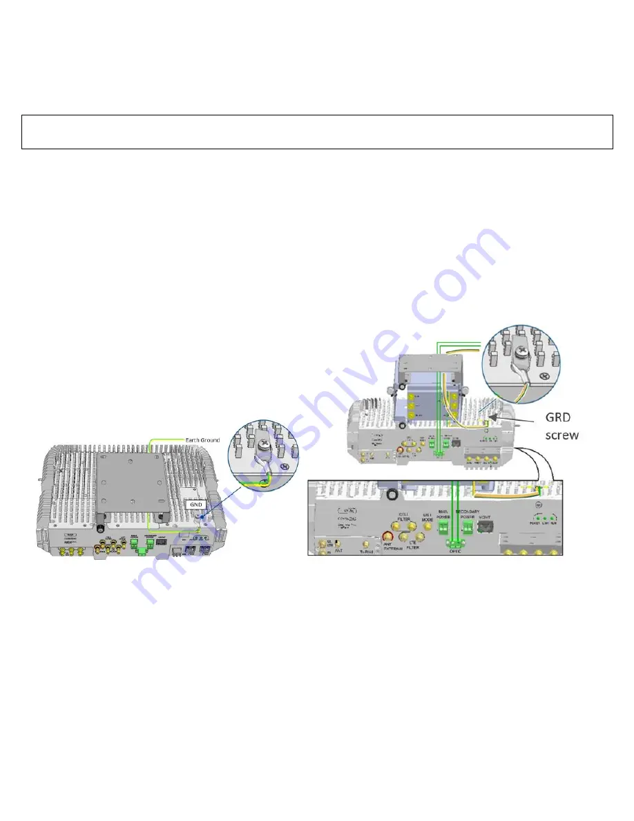
Grounding Connection
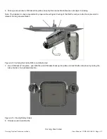
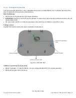
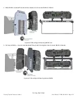
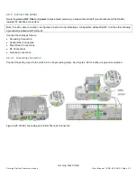
Connect the earth ground to the unit
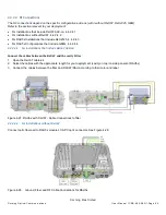
’s 8-32 x 3/8 grounding screw. See Figure 4-25 for location of ground connection.
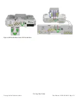
Figure 4-25. RAU5x Grounding and optical fiber pair Connection

