Corning Restricted
C o r n in g O pt ic a l Com m un ic at io ns
Us e r Man u al I C MA - 4 82 - A E N I P a g e 7 3
7.2.1
Connect RxU2325 and/or GEM to the RAU5x
To install RxU2325 and/or GEM plug-in module in RAU5x :
1. Plug-in module as follows:
•
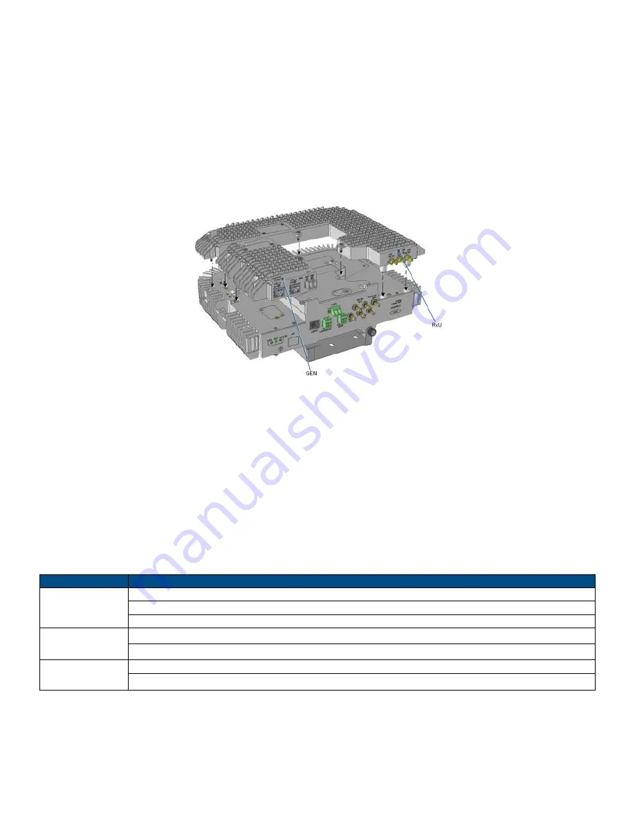
RxU2325
– plug-in RxU2325 into right
side of the RAU5x as indicated in Figure 7-2 (area highlighted in green in inset)
and close the two screws to secure in place.
•
GEM - plug-in GEM into left
side of the RAU5x as indicated in Figure 7-2 (area highlighted in blue in inset) and close
the screw to secure in place.
Figure 7-2. Plugging-in RxU2325 and GEM
NOTE: RxU67 is installed instead of GEM
2. For units with broadband antenna
– close antenna.
3. For RxU2325:
•
With external antennas from other vendor - connect Rx
U “EXT. ANT.” QMA connector to an external antenna for MIMO
coverage
•
With Corning external antenna
– connect RxU “EXT. ANT.” QMA connector to the external antennas’ “RxU” QMA port
using RF jumper.
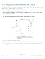
Note: If cavity filter connections are required for the LTE 700 MHz band
–
refer to Section 5 for relevant connections.
4. For GEM
— refer to Section 4.4.2.4.4 for GEM connections.
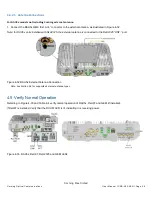
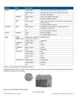
5. Verify that RAU5x LEDs on front panel indicate normal operation status:
LED
Description
LINK
Steady green - Optical link power to/from the RAU is normal
Blinking green - Optical power from remote is lower than required
Off
– No optical link detected
POWER
Steady green - Input power within required range detected
Off
– No power supplied to RAU
RUN
Blinking green
– RAU boot up sequence complete and module SW up and running
Off
– No power supplied to unit
Table 7-4. RAU5x LED Descriptions
6. For units installed with top bracket
– push lift bracket into place.
7. For units with top bracket cap
– replace cap (see Section 4.3.2.3).


