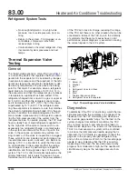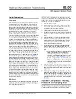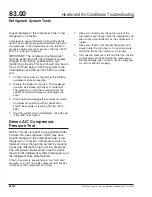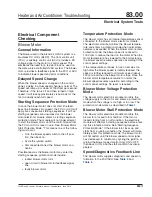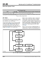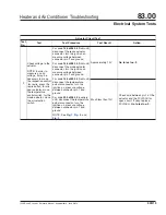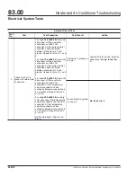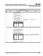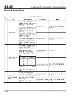
Test the Actuator Stepper Motor
NOTE: The stepper motor has four windings,
each with an in-series diode. The stepper motor
can be tested on or off the vehicle.
1.
Connect the stepper motor tester to the stepper
motor. If the stepper motor is being tested while
on the vehicle, disconnect the electrical connec-
tor from the stepper motor.
For locations of the actuators and actuator re-
placement instructions, see
2.
Set the digital multimeter to read
milliamps
(mA) DC
. Make sure that the test leads on the
multimeter are in the appropriate jacks for mea-
suring amperage.
3.
Connect the positive lead from the multimeter to
the red jack on the stepper motor tester.
4.
Connect the negative lead from the multimeter to
the black jack. See
5.
Press the toggle switch to NORMAL.
6.
Set the rotary switch to position 1 and note the
reading on the multimeter.
7.
Move the toggle switch to REVERSED and note
the reading on the multimeter.
8.
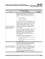
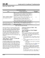
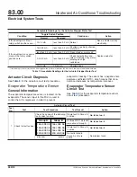
Repeat the previous three steps for the 2, 3, and
4 rotary switch positions on the tester. Compare
your readings to the readings in
9.
If your readings do not match the readings in
, replace the actuator. For instructions,
see
10. If the stepper motor was tested on the vehicle,
connect the electrical connector to the stepper
motor.
REVERSED
NORMAL
J−46315
Rev. 2
Actuator motor coil/diode circuit
1
2
3
4
METER
Set meter to read mA
SPX KENT−MOORE
11/26/2002
1
2
f831554
1.
Toggle Switch
2.
Rotary Switch
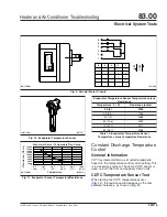
Fig. 4, Actuator Stepper Motor Tester
12/06/2002
f831556
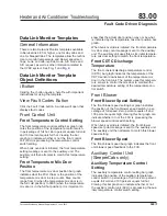
Fig. 5, Place the Negative Lead to Pin 6 of the Stepper
Motor Tester Lead
11/27/2002
f831555
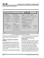
Fig. 6, Testing a Stepper Motor
Heater and Air Conditioner Troubleshooting
83.00
Electrical System Tests
122SD and Coronado Workshop Manual, Supplement 9, June 2014
330/11


