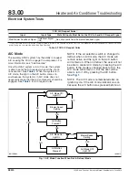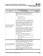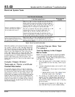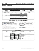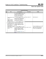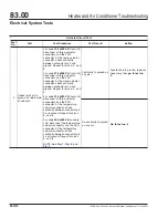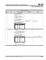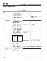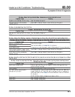
Evaporator Temperature Sensor Circuit Test
Test
No.
Test
Test Procedure
Test Result
Action
2
Check sensor
reference voltage.
Disconnect the evaporator
sensor.
Turn the ignition on and measure
the voltage across the sensor
connector pins (harness side).
The voltage should be 5V if the
circuit and FCU are operating
correctly.
5V
Perform "Evaporator
Temperature Sensor Test."
Less than 5V.
Check for open circuit in sensor
signal and ground wires. If okay,
replace FCU.
Go to test no. 3
.
3
Verify repair.
Verify that repair resolved the
problem.
Problem solved.
Done.
Problem unresolved.
Repeat test no. 1
.
Table 9, Evaporator Temperature Sensor Circuit Test
Evaporator Temperature Sensor
Test
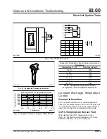
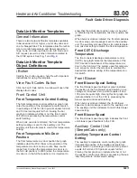
When testing the evaporator temperature sensor
(
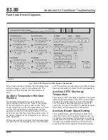
), the resistance will decrease as the tem-
perature increases, as shown in
1.
Remove the sensor and place it in a cup of ice
water.
2.
After the sensor has been in the ice water for
five minutes, measure the sensor resistance.
The resistance should be 9000 ohms at 32°F
(0°C). See
3.
If the resistance differs significantly, replace the
sensor.
08/16/2002
f831470a
1
4
6
2
3
5
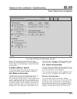
1.
Mode Actuator
2.
CDTC Temperature Sensor
3.
Evaporator Temperature Sensor
4.
Recirculation Actuator
5.
Blower Motor
6.
Temperature Actuator
Fig. 7, Cab HVAC Assembly
08/27/2002
f831539
2
3
4
1
1.
CDTC Sensor
2.
Temperature Actuator
3.
Auxiliary Control Unit (ACU)
4.
Blower Motor
Fig. 8, Auxiliary HVAC Assembly
Heater and Air Conditioner Troubleshooting
83.00
Electrical System Tests
122SD and Coronado Workshop Manual, Supplement 9, June 2014
330/18

