C
ELECT
DRT 2
Digital ProgrammableThermostat
for
Weekday/Weekend Setting
Instruction Manual
www.coronadocontrols.com
CORONADO CONTROLS LTD
BOLTON BL1 2PT
TABLE OF CONTENT
A. Installation and Mounting....................
1. Installation........................................
4
3. Mounting........................................... 5
3
B. Start/Reset..................... .................. 6
C. Normal Time Mode............................. 7
D. Normal Time Setting Mode.................. 8
E. Factory Defined Programs.................. 9
F. Set Program...................................... 10
1
13
DRT 2 LCD Programmable Thermostat
A. Installation and Mounting:
Caution:
Turn off DRT 2 and the electrical devices (e.g.
heater,cooler)which will be connected before
installation. It is highly recommended that the
installation procedure is processed by trained
personnel.
1. Installation Location:
2
3
12
2. Wiring:
3. Mounting:
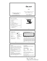
There are 3 wiring terminals at the bottom of DRT 2,
labeled as "Com"(Common), "NO"(normal open)
and "NC"(normal close). Connect heater or cooler to
the "NO" and "Com" terminals. Leaves unused hole
blank.
- Wire the correct cables to the terminal block
according to the circuit diagram which is attached
inside the thermostat top cover.
- Push all cables back into wall prior to fixing to
avoid trapping wires.
- It is recommended that a 5A fuse is fitted.(Please
refer to the wiring diagram on the last page.)
Using the accessory screws and wall anchors
provided, mount DRT 2 with the key-hole at the
back. The thermostat should be mounted on the wall
as shown in step 3 of Figure1. Install the cover on
DRT 2 as shown in step 4 of Figure1.
14
Control Off mode:
The LCD is fully turned off. The heater/ cooler is
switched off, irrespective of the current control
temperature setting.
Delay / No Delay jumper:
Heater
Cooler
No delay
10sec
4mins
Delay
4mins
4mins
Choose the Delay option if compressor heat is
connected.
12-hours / 24-hours mode jumper:
When the 12-hours option is selected, the time is
shown in 12-hours mode. Otherwise, the time is
shown in 24-hours mode.
Heater / Cooler jumper:
Select the heater option when a heater is connected
to DRT 2. Select the cooler option when a cooler is
connected to DRT 2.
I.Jumper selection:
2
2. Wiring................................................
G.Temporary/Permanent Override Mode..11
H. Control Off/ Sleep Mode..................... 12
I. Jumper Selection.............................. 13
J. Specification.................................... 14
Terminal block connecting Label:
J. Specification:
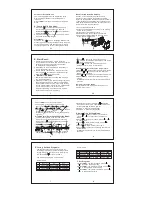
1.Temperature measurement: 0.0 - 40 C
(0.1 C/step)
2.Accuracy:
0.5 C
3.Temperature control range: 5.0 - 35.0 C
(0.5 C/step)
4.Switching:
24..250VAC 50/60Hz
5(3.5)A max
5.Terminals:
2.5mm cable
6.Electronic control:
Type 2.B action
7.Battery:
2 x 1.5V AAA alkaline
battery
8.Operating temperature:
0 - 50 C
9.Storage temperature:
-10 - 60 C
10.Sensing Element:
NTC thermistor
2
°
°
°
°
°
°
°
The thermostat should be mounted on an inner wall
1.5m above the floor in position where it is readily
affected by changes of the general room temperature
with freely circulating air. Prevent direct exposure to
sunlight; dripping or splashing area. Do not place this
unit at a location where air circulation is low, or where
it has great temperature changes (e.g. near door). Do
not place the thermostat near heat/cool generating
sources.
K
P/N: FLT38C~~21
100g Instruction Manual


