Page 2
M
Mode
Button
Down
Button
Up
Button
Initial Setup
The setup function is normally only used
for a new installation. It is not required to
follow this procedure every time the
instruments are turned on.
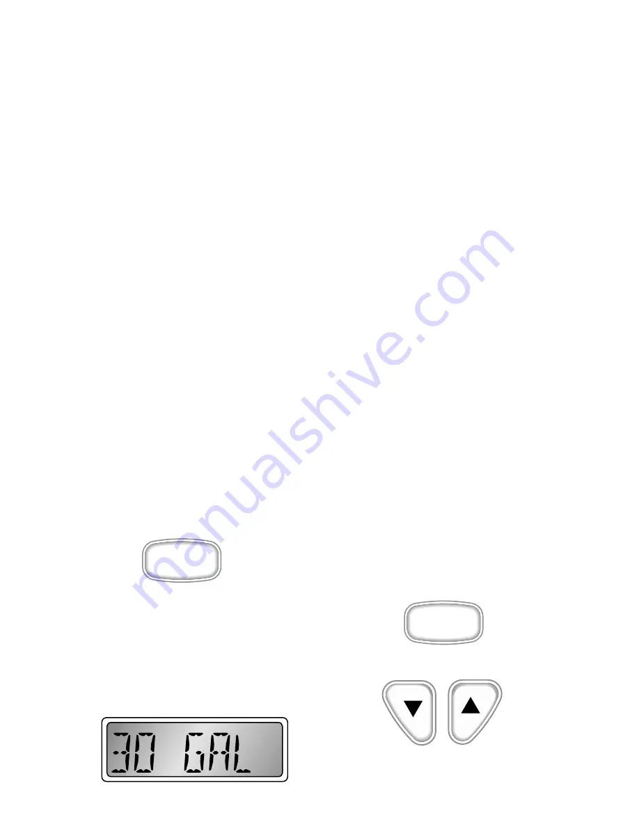
The tachometer is used to initialize the
fuel tank size required for the fuel
management function. Press the “mode M”
button while the power is turned on, to
enter the “setup” mode.
The LCD will show the current fuel tank
size selection. The choices are displayed
with the “Up” or “Down” buttons. After
selecting the closest tank size, press and
hold the “mode M” button for 3 seconds to
save the selected size and start normal
instrument operation.
Select from one of the following fuel tank
capacity options:
29 gallon
30 gallon (default)
35 gallon
39 gallon
50 gallon
Operation
General
The Faria® Serial Bus™ system is
designed to receive information from the
engine ECU and various individual
sensors throughout the boat. This
information is transformed into digital
data which is distributed to analog and
digital instruments via a single cable
consisting of two shielded, twisted pairs of
conductors.
Each instrument selects the data which is
applicable and displays it as if it was being
received from the sender directly. One of
the two pairs of conductors carries the data
while the other pair of conductors carry
the power for the instruments.
The tachometer and speedometer each
have three push buttons which allow the
different functions of each instrument to
be activated. Following is a description of
these functions.
M
Mode
Button
System
The system consists of:
• One Gateway box to interface with
MEFI IV ECU and external senders
and sensors.
• One 5” Tachometer with Fuel
Monitor
• One 5” Speedometer with Depth
Sounder
• optional second 5” Speedometer
• Various 2” instruments, including but
not limited to
• Voltmeter
• Oil Pressure gauge
• Fuel gauge
• Engine Temperature gauge
• others as specified.
Summary of Contents for Sport Nautique 216
Page 4: ...iv...
Page 40: ...Notes...
Page 42: ......
Page 48: ...3 6...
Page 50: ...Inside Engine box on Fuel Tank Water Strainer Fuel Fill Throttle Control 4 2...
Page 51: ...Transom Warning Label Cross Member Boarding Platform Engine 4 3...
Page 52: ...Flame Arrestor Flight Clip Walk Thru Windshield Dash Pod 4 4...
Page 53: ...Fuel Control Cell 4 5...
Page 54: ...Side Console 4 6...
Page 55: ...Flight Control Tower 4 7...
Page 56: ...Capacity Plate 4 8...
Page 70: ...6 12...
Page 76: ...8 4...
Page 82: ...9 6...


