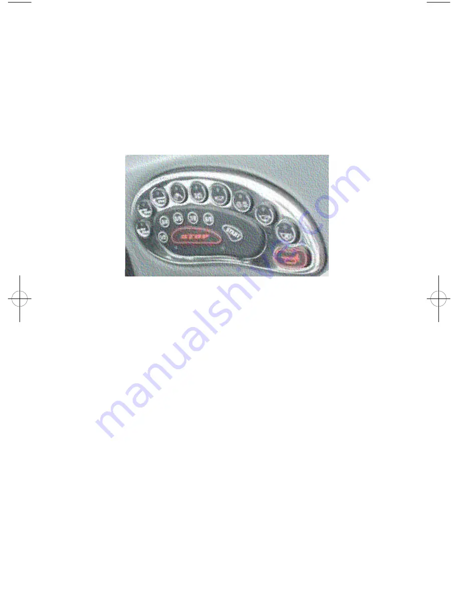
include: air/water temp gauge, clock, depthfinder,standard stereo remote
control or digital stereo remote control, Correct Craft Cruise or Perfect Pass
Digital Pro speed control. The optional gauges can be positioned on the
console located to the right of the drivers knee.
CAUTION: The keypad and switch control box will be damaged beyond repair if
the boat battery cables or the main power leads to the keypad and switch control
box are reversed. Be sure to use caution and avoid reversing these connections.
Keyless Ignition and Serial Switching
The ignition switch system is keyless and has three modes of operation.
Locked Mode
When the boat battery is first connected, the unit is in locked mode. In this
mode, the horn, bilge pump, bilge blower, and code buttons are operational.
Unlocked Mode
Unlocked mode is entered after the user successfully enters the user code,
presses, and releases the start button. When the code keys are pressed, the
system indicator light to the right of the start button will turn on while the key
is pressed down. This indicates the button has actually been pushed. When
the system is unlocked, power is supplied to the boat and the system indicator
light will turn on. At this point all keypad buttons are operational and
actuating these buttons will control the corresponding boat functions. To put
the unit back in locked mode, the user must successfully enter the user code
then press the stop button. When the code keys are pressed, the system
indicator light to the right of the start button will turn off while the keys are
pressed down. Power will be cut to all of the accessories with the exception
of the horn, bilge pump, bilge blower and code buttons.
Run Mode
First enter the unlocked mode.
Pressing and releasing the start button quickly will put the unit in run mode.
When this is done, power is supplied to the engine ignition, but the engine will
1.2
Keyless Ignition
Sport Nautique 216 2003.qxd 7/29/02 11:22 AM Page 1.2
Summary of Contents for Sport Nautique 216
Page 4: ...iv...
Page 40: ...Notes...
Page 42: ......
Page 48: ...3 6...
Page 50: ...Inside Engine box on Fuel Tank Water Strainer Fuel Fill Throttle Control 4 2...
Page 51: ...Transom Warning Label Cross Member Boarding Platform Engine 4 3...
Page 52: ...Flame Arrestor Flight Clip Walk Thru Windshield Dash Pod 4 4...
Page 53: ...Fuel Control Cell 4 5...
Page 54: ...Side Console 4 6...
Page 55: ...Flight Control Tower 4 7...
Page 56: ...Capacity Plate 4 8...
Page 70: ...6 12...
Page 76: ...8 4...
Page 82: ...9 6...


