background image


Corsham   Technologies,   LLC   

www.corshamtech.com   

617   Stokes   Road,   Suite   4-­‐299   

Medford,   NJ      08055   


KIM-­‐1   I/O   Board   


Revision C or Later Boards 

March 2013 

 
Thank you for purchasing a KIM-1 I/O expansion board, which has been one of our most popular 
products.  It was developed as a result of what capabilities we wanted to add to our KIM-1 
collection to make it easier to use and interface with more common communication standards. 
 
This board has been sold with few changes for many years, but the revision C board has a number 
of changes to address needs of our customers: 


Power connector now has three terminals instead of four. 


A power LED has been added. 


The audio connectors are now a more common 1/8

th

 inch. 


The KBD/TTY option is now set via a switch instead of a jumper. 


Smaller board. 


Silkscreen labels instead of copper. 

 
For references to direction through this document, the board is assumed to be in “normal” 
position, with the edge connector facing to the right, ready to plug into the KIM’s Application 
connector.  The Application connector is along the lower, left-hand edge of the KIM.  The 
Expansion connector is the upper connector. 
 

Installation 

 
We’re going to begin the installation in a somewhat unusual way… we’re not going to plug the 
board into the KIM-1 at first.  Trust me, this will make sense eventually. 
 
The first step is to connect a 5 volt power supply and ground to the green J1 connector at the 
upper left hand corner of the board.  There are three terminals on this connector, each of which is 
labeled just to the left of the connector. Make sure you connect a well-regulated 5 volt DC supply 
that is capable of at least the 1.2 amps required of the KIM.  If you wish to use the cassette 
interface, you also need to connect a 12 volt supply on the appropriate jack on J1.  The KIM-1 
does not use 12 volts except for the cassette interface, so if you don’t need this, then there is no 
need for the 12 volt supply. 

Summary of Contents for KIM-1

Page 1: ...s document the board is assumed to be in normal position with the edge connector facing to the right ready to plug into the KIM s Application connector The Application connector is along the lower left hand edge of the KIM The Expansion connector is the upper connector Installation We re going to begin the installation in a somewhat unusual way we re not going to plug the board into the KIM 1 at f...

Page 2: ...the KBD setting Now it s time to give it a test Apply power and press the RS key on the keypad Your KIM should be displaying data on the LED displays above the keypad just like usual Connecting an RS 232 Terminal By default the KIM talks to the user via the keypad and LED display on the main board To force KIM to communicate via the TTY port you need to connect a suitable device set a switch and d...

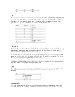
Page 3: ... adjusting the tape s PLL potentiometer on the main KIM board such as PLL SET from the excellent book The First Book of KIM If you own a KIM you really should have a copy of that book Jumpers and Connectors J1 This is the power connector The KIM needs 5 volts at approximately 1 2 amps In order to use the cassette I O circuitry it also needs 12 volts The top connector on J1 is for the 5 VDC connect...

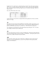
Page 4: ... the KIM s L pin AUDIO IN This should be connected to the output from the cassette recorder J6 AUDIO OUT is connected to the center pin of JP2 Depending on where the jumper on JP2 is placed either AUDIO OUT HI pin P or AUDIO OUT LO pin M is connected to J6 This jack is connected to the microphone input on the recorder Note that if nothing is plugged into J6 and J4 then the audio out and audio in l...

Page 5: ...8K of memory decode logic or not By default the jumper should be in the INT position This grounds pin K DECODE ENAB so that the on KIM memory decode logic is always active This is the normal configuration If you jumper the center and EXT pins then decode signal comes from pin 10 of J5 Use this is you externally decode the top three address bits JP2 This selects the audio level to the tape recorder...

Reviews: