15
15
PB7
16
16
PB5
J5
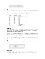
This is memory block decode header. If you refer to Chapter 6 in the “KIM-1 USER MANUAL”,
you’ll see an explanation of the lines K1 to K4, and how to go beyond the first 8K block that is
decoded by the KIM memory decode logic. This header brings all the associated pins to one
place for easy expansion. This header is used for our 60K RAM board.
J5 Pin
KIM pin
Name
1
1
Ground
2
B
K0
3
C
K1
4
D
K2
5
E
K3
6
F
K4
7
H
K5
8
J
K7
9
From pin 2 of J9
10
To JP1
J4 and J6
These are the audio lines to/from an external audio source, typically a cassette recorder for saving
and restoring programs or data. J4 connects to the KIM’s L pin, AUDIO IN. This should be
connected to the output from the cassette recorder.
J6, AUDIO OUT, is connected to the center pin of JP2. Depending on where the jumper on JP2
is placed, either AUDIO OUT HI (pin P) or AUDIO OUT LO (pin M) is connected to J6. This
jack is connected to the microphone input on the recorder.
Note that if nothing is plugged into J6 and J4, then the audio out and audio in lines are connected
together. This can be used for adjusting the KIM’s PLL.
TTY
This is the serial connector. All signals are at RS-232 levels, and connected to the KIM’s TTY
interface.
Pin
Use
2
RS-232 data out
3
RS-232 data in
5
Signal Ground
J9 and SW1
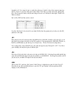
The KIM brings four lines, K1 to K4, to the Application connector to make it easy to add four
more KB of RAM. The switches on SW1 select which bank(s) of memory has the chip select


