background image

MOBILTEX® DATA LTD. 

Calgary, Alberta 

www.corTalk.com 

TITLE:  

uDL2 Configuration and Operation Guide


DOCUMENT NO.: 

UDL2-MAN-001


SHEET: 

17 of 28


REV: 

1.07 


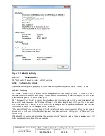
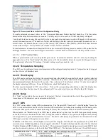
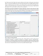
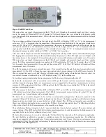
Figure 22 Overcurrent Detector Retries Configuration Dialog 

To enable automatic reconnect retries, set the ‘Overcurrent Reconnect Retries Enabled’ check box.  The four values 
shown set the delay between retries, in seconds.  If a delay entry is set to a value of 0, that retry delay is skipped. 

Care should be taken in using this capability as the current path relay and sense resistor will degrade with each over-
current disconnection event.  The number of retries and the delays should be tailored to minimize the number of over-
current events.  By default, the unit is set to 300s (5min), 900s (15min), 1800s (30min), and 3600s (1hour) between 
reconnection attempts.  Also by default, the reconnect retries feature is disabled. 

For each automatic reconnection attempt that fails due to overcurrent still being present, a marker will be placed in the 
datalogger memory.  If a reconnect attempt is successful (i.e. current back to normal levels), the retry counter is reset. 

4.3.2.3.2


CH2 Potential Mode 

When  in  potential  mode,  the  second  potential  point  can  be  measured  for  both  DC  and  AC  values  by  checking  the 
appropriate boxes.  The “Inv. Polarity” checkbox can be set if it is desirable for data to be recorded with opposite signs.  
This option only affects the DC readings.  Potential readings are always made in volts. 

4.3.2.4  Temperature Sampling 

The uDL2 may be configured to measure temperature at the configured sampling interval.  Temperature may be logged 
in either Celsius or Fahrenheit units. 

4.3.2.5  Time Display 

The uDL2 can be configured to display the current time during the initial 60 seconds after the analog cable is attached 
and for 5 seconds after the analog cable is removed.  After the analog cable is attached, the display will cycle through 
the measurement data and the time for 60 seconds.  Time is shown in 12 hour format with an ‘A’ in the lower right of 
the display indicating AM times.  To enable this feature, check the ‘Enabled’ box. 

The time may be displayed in UTC or local time.  Click on the  corresponding radio button to select the display time 
type.  For local time, the time zone of the configuration PC is used to select time zone offset for the uDL2 display. 

4.3.2.6  Notes 

The “Notes” section allows the user to enter freeform text. This text is inserted into the start of the exported CSV file. 
A maximum of 100 characters can be entered into this field. 

4.3.2.7  GPS 

The “GPS” section allows setting GPS synchronization.  The “Require GPS Time Lock To Start Sampling” forces the 
uDL2 to wait until accurate time is received from the GPS satellites before starting data recording after the analog cable 
is inserted.  This option would be checked when high accuracy time stamps are needed on the measurement points.   

When checked, the “Disable Long Term GPS Time Synchronization” option stops the uDL2 from periodically turning 
on the GPS receiver to maintain accurate time.  This option would be enabled to save power when high accuracy timing 
is not required for a particular measurement session.  The uDL2 will attempt to synchronize the internal clock to the 
GPS signal every hour if this option is not enabled. 

In addition, with firmware v1.06 and higher, it is also possible to apply a limit check to the position accuracy of the GPS 
receiver before a latitude/longitude position is logged by the uDL2.  To enable this functionality, check the box labelled 
“Enabled Minimum EHPE Validation For Position”.  The minimum estimated horizontal position estimate (EHPE) limit 
can then be entered, in meters, in the box labelled “Min EHPE (m)”.  The limit must be between 3.0 and 200.0 meters.  

Summary of Contents for uDL2

Page 1: ...D Calgary Alberta www corTalk com TITLE uDL2 Configuration and Operation Guide DOCUMENT NO UDL2 MAN 001 SHEET 1 of 28 REV 1 07 uDL2 Data Logger for CP Coupons Configuration and Operation Guide Print Date March 26 2018 ...

Page 2: ...Revision 1 07 Name Location Job Function Signature Date Tony da Costa Calgary Engineering Manager Jerry Chilibecki Calgary Director of Engineering REVISION HISTORY Rev Start Date Approval Date Description Prepared By Draft 0 01 Feb 19 2013 First draft Tony da Costa 1 00 Feb 20 2013 Initial release Tony da Costa 1 01 April 9 2013 Added coupon test station connection picture Added CC Tech coupon tes...

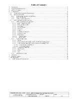
Page 3: ...Config From uDL2 13 4 3 1 2 Write Config To uDL2 13 4 3 1 3 Link Status 13 4 3 1 4 Factory Options 13 4 3 1 5 Firmware 14 4 3 1 6 Serial 14 4 3 1 7 Read Write Config File 14 4 3 1 8 Set uDL2 Clock 14 4 3 1 9 Read Faults 14 4 3 1 10 Detailed Status 14 4 3 1 11 Reboot uDL2 15 4 3 2 Configuration Group 15 4 3 2 1 Timing 15 4 3 2 2 Coupon Potential Sampling CH1 or Potential Sampling CH1 16 4 3 2 3 Cou...

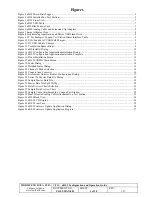
Page 4: ...n Application Installation Dialog 11 Figure 15 uDL2 Configuration Application Installation Complete 11 Figure 16 Driver Installation Screen 12 Figure 17 uDL2CONFIG Main Screen 13 Figure 18 Faults Dialog 14 Figure 19 Detailed Status Dialog 15 Figure 20 Channel 2 Mode Selection 16 Figure 21 Coupon Area Converter 16 Figure 22 Overcurrent Detector Retries Configuration Dialog 17 Figure 23 Extract To M...

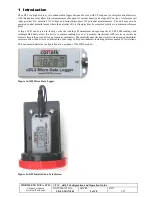
Page 5: ... potential mode where the potential of two structures may be measured relative to a common reference point A large LCD can be used to locally verify the readings Measurement storage capacity of 2 000 000 readings and rechargeable battery allow the device to capture readings for over 4 months An internal GPS receiver provides an accurate time reference and site geo location coordinates The small ph...

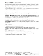
Page 6: ...ct manual for further ratings information before making connections to the product Do not use an input marked with measurement category I for measurements within measurement categories II III or IV Do not connect category II inputs directly to mains a Class 2 CSA UL transformer must be used for isolation Do Not Operate Without Covers Do not operate this product with covers or panels removed Avoid ...

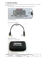
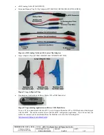
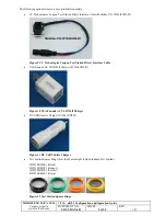
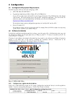
Page 7: ...t Contents The Mobiltex part number for the uDL2 kit is A20A03UDL20 non USA or A20A03UDL21 USA The following items are included in each kit uDL2 Data Logger for CP Coupons Unit A15000UDL20 non USA A15000UDL21 USA Figure 3 uDL2 Front View uDL2 USB Cable W164IFUDL01 Figure 4 uDL2 USB Cable uDL Black Fabric Case H20712UDL01 Figure 5 uDL Black Fabric Case ...

Page 8: ...lips H27400112BK H27400112RD H27400112BU Figure 7 Large Alligator Clips Programming Application and Driver Media CD or USB flash drive Figure 8 Programming Application and Driver USB Flash Drive To use a PC to communicate with the uDL2 you will require the media CD or USB flash drive that shipped with the uDL2 The media contains drivers and the uDL2 configuration application If you do not have the...

Page 9: ... Interface Cable Mobiltex P N W164I0UDL03 Figure 9 CC Technologies Coupon Test Station Direct Interface Cable USA Canada AC USB Wall Charger P11606UDL01 Figure 10 USA Canada AC USB Wall Charger DC USB Vehicle Charger P11606UDL02 Figure 11 DC USB Vehicle Charger Test Station Spacer Rings Provide More Height Inside Standard Test Station H23510RMU01 Black H23530RMU01 Orange H23540RMU01 Yellow H23550R...

Page 10: ...he application software and drivers require that the PC be running Windows XP SP3 or higher for an operating system The PC must have an available USB port 4 2 Software Installation To install the configuration application and driver software insert the media CD or USB flash drive that came with the configuration interface into the appropriate drive or USB port on the PC If autorun is enabled on th...

Page 11: ...in the installation screens clicking Next to move to the next screen each time Some screens may pause for tens of seconds as the Windows installation procedure is processing The final screen should show the dialog in Figure 15 Click Close to complete the installation Figure 15 uDL2 Configuration Application Installation Complete A shortcut to the configuration application and the uDL2 manual are c...

Page 12: ...he following screen should display Follow the installation instructions presented by the driver installer application Figure 16 Driver Installation Screen Once the driver installer completes you may then plug in the uDL2 through the USB cable into an available USB port on the PC 4 2 3 Adobe Acrobat Reader XI Adobe Acrobat Reader XI is provided on the installation media to allow viewing of the PDF ...

Page 13: ...g or not connected an error dialog will pop up If it is not connected simply connect the USB cable to the computer and try again If the uDL2 LCD display is showing bSY wait until USb is shown before attempting to read the configuration from the uDL2 Once communications have been established with the uDL2 the operational parameters can be configured for the requirements of a particular measurement ...

Page 14: ...led in the configuration the uDL2 clock should be set at least once before data acquisition is attempted Beyond that the clock should be updated periodically to resynchronize the clock to actual time The internal clock of the uDL2 model can be expected to drift as much as 10s each month without GPS synchronization The uDL2 will maintain the real time clock as long as the battery is not fully deple...

Page 15: ...ep mode to conserve battery power The Disconnect Cycle Period determines how often the coupon interruption relay will be opened for instant off and de polarization measurements The Disconnect Duration value is how long the relay is left open for each disconnect event After each relay transition the uDL2 will wait before taking the next DC potential measurement this wait time is determined by one o...

Page 16: ...the uDL2 G2 G3 ranges Select the range based on the expected maximum coupon current and the range specifications from Appendix A Note that only the uDL2 G2 and uGL2 G3 models supports all three ranges earlier versions of the hardware only support the medium and high ranges The low range radio button will be disabled for units that do not support that range The Inv Polarity checkbox can be set if i...

Page 17: ...attached and for 5 seconds after the analog cable is removed After the analog cable is attached the display will cycle through the measurement data and the time for 60 seconds Time is shown in 12 hour format with an A in the lower right of the display indicating AM times To enable this feature check the Enabled box The time may be displayed in UTC or local time Click on the corresponding radio but...

Page 18: ... GMT time or in local time Local time is based on the time zone selected in the operating system of the computer being used to extract the data When the Extract To Master Data File button is clicked the following save as screen will prompt the user for the storage filename Figure 23 Extract To Master Data File Dialog The stored file is saved in a comma separated value CSV format that can be import...

Page 19: ...MOBILTEX DATA LTD Calgary Alberta www corTalk com TITLE uDL2 Configuration and Operation Guide DOCUMENT NO UDL2 MAN 001 SHEET 19 of 28 REV 1 07 Figure 24 Sample Master Data File ...

Page 20: ...ith processing applications are encountered For example Microsoft Excel 2003 has a limit of 65 536 rows while newer versions have a limit of 1 048 676 rows Enter the maximum number of lines rows desired in the output files and then click the Split button to break the input files into smaller files The output files will have the same names as the input files but suffixed with an incrementing number...

Page 21: ...ed click on the Zoom All button When viewing DC Wave capture segments the currently displayed data segment may be selected by clicking the Previous Next First or Last buttons under the Wave Print Segment area These buttons do not appear for other preview chart types The current chart view may be saved to a file Click the Save Chart button to save a bitmap of the chart The bitmap may be saved in JP...

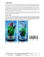
Page 22: ...osition the connector internal sealing o ring The cable is released by pulling back the black ring which has the white arrow of the connector The measurement cable has three banana plugs to allow connection directly to banana jacks There are also three extension clip wires included that can attach to the banana plugs of the measurement cable The unit can be operated in two modes coupon mode and du...

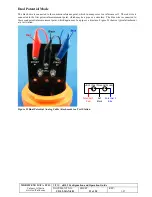
Page 23: ...y cases is a reference cell The red wire is connected to the first potential measurement point which may be a pipe or a structure The blue wire is connected to the second potential measurement point which again may be a pipe or a structure Figure 29 shows a typical attachment at a test station V1 V2 Ref Black Potential 2 Blue Potential 1 Red uDL2 Dual Potential Mode Figure 29 Dual Potential Analog...

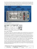
Page 24: ... digits of measurement information When the analog cable is first attached the uDL2 will enter a real time measurement display mode for a period of 1 minute During this time the uDL2 doesn t store information to memory and it provides real time measurement data on the LCD which is updated every 2 seconds The SAMPLE icon continuously illuminates during this real time display mode After the real tim...

Page 25: ...f the over current disconnect is activated the relay will remain open until the analog is detached and then re inserted An over current disconnect is indicated by an LCD display showing O in the reading area To stop data logging simply unplug the measurement cable The device will automatically shut off Each time the measurement cable is inserted the device will begin the 1 minute real time measure...

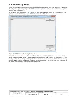
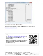
Page 26: ...lication and execute the uDL2 Firmware Update application from the Windows start menu The dialog in Figure 33 will be shown Figure 33 uDL2 Firmware Update Application Dialog To start the firmware update process first ensure that the uDL2 is connected to a USB port on the computer Next click on the Program Firmware button The application will indicate progress as the firmware is downloaded to the u...

Page 27: ... latest uDL2 software package may be downloaded from the Mobiltex web site at the following URL http www mobiltex com cathodic udl2 uDL Registration Visit www mobiltex com service registration html and register your uDL to receive notification of free firmware updates Information provided will be used for the sole purpose of sending notification of firmware updates and will never be shared or sold...

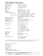
Page 28: ...red common Lightning Immunity Survives multiple 20KV 10mS surges Temp Measurement Accuracy 4 C 7 F over 20 to 60 C 4 to 140 F Potential DC Accuracy over 20 to 60 C 4 to 140 F 0 55 5mV Potential AC Accuracy over 20 to 60 C 4 to 140 F 1 5mV 20mV floor Current DC Accuracy over 20 to 60 C 4 to 140 F 0 5 2uA low range 0 5 20uA med range 0 5 750uA high range Current AC Accuracy over 20 to 60 C 4 to 140 ...

Reviews: