MOBILTEX® DATA LTD.
Calgary, Alberta
www.corTalk.com
TITLE:
uDL2 Configuration and Operation Guide
DOCUMENT NO.:
UDL2-MAN-001
SHEET:
22 of 28
REV:
1.07
5
Operation
There are no user controls on the actual uDL2. Data acquisition cannot be scheduled to start at a particular date and
time. Instead, the device automatically powers up when the measurement cable is installed and immediately starts data
acquisition activities. The device ceases data acquisition and powers down when the measurement cable is removed.
The waterproof connector that mates to the uDL2 has an automatic physical locking function. The white arrow on the
cable should align with the black arrow on the top graphic overlay of the uDL2. When the cable is inserted, it will “click”
to indicate that the connector is locked in place. New cables may require application of additional force until the “click”
is heard in order to properly position the connector internal sealing o-ring. The cable is released by pulling back the
black ring (which has the white arrow) of the connector.
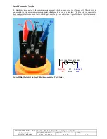
The measurement cable has three banana plugs to allow connection directly to banana jacks. There are also three
extension clip wires included that can attach to the banana plugs of the measurement cable. The unit can be operated in
two modes: coupon mode and dual potential mode.
Coupon Mode
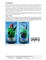
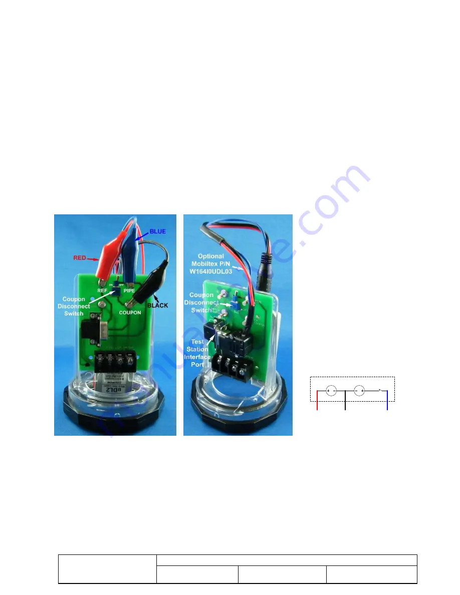
The black wire is connected to the coupon, the blue wire is connected to the structure (pipe), and the red wire is connected
to the reference half-cell.
When connected to a coupon test station, ensure that the test station coupon disconnect
switch is left in the “open” or “off” position; otherwise, current will not flow through the uDL2 internal current
sense.
Figure 28 shows typical attachments to a coupon test station. The optional W164I0ULD03 cable allows direct
attachment to the DE-9P test port connector on the CC Technologies Coupon Test Station.
V
A
Coupon
Black
Pipe
Blue
Ref Cell
Red
uDL2 (Coupon Mode)
Figure 28 Sample Cable Attachment to a Coupon Test Station

