4
Before operating the machine, check that switches are in good operating
condition. Attention: the motor has no cut-off function. Do not use it for
overloads. If the machine is unable to lift an item, do not attempt to force it.
Switch the motor off to allow it to cool, reduce the load, and lift again.
Position-Limit Safety Device:
The position-limit safety device is designed to prevent capacity limits being
exceeded when lifting or lowering a load.
Do not use it as a travel switch and never dismantle. The hoist brake system
The hoist brake system is factory-adjusted to work within the rated load
conditions. After long use, the rubber in the brake system will become worn
and the brake will no longer work as it should. If you feel that your hoist can
no longer lift the load for which it is intended, please contact your dealer to
replace the friction plate.
The electric hoist features up and down limit-position safety devices. When
a load is hoisted to the limit-position level, the machine will stop lifting.
Conversely, if the downward movement is too fast, the safety switch will be
triggered and the machine will stop working. The down safety switch is installed
on the side of machine. There must be at least 2 turns of wire rope on the spool
when the down safety switch triggers. Otherwise, it is out of adjustment and
you should have it reset at your local dealer.
Please ensure that you check all easily-wearing parts as mentioned above every
6 months to ensure the safety of the operator and the machine.
EXTENSION LENGTH
CABLE SECTION
Up to 20 m
1.5 mm
From 20 to 50 m
2.5 mm
3. MAINTENANCE
Periodically CHECK that the motor cut-off switch and push button switch are
in good working condition. Please check extent of wear and tear on the hoist
and perform regular maintenance. Check normally once a year.
Ensure that all moving parts are adequately greased or oiled: e.g. the hook,
drum shaft, gearbox and shaft etc. Do not grease the cable!
Note: Abrasion of the hook: Check abrasion of the hook at each maintenance; if the
wear/abrasion exceeds 10% of the original size, replace the hook with a new one.
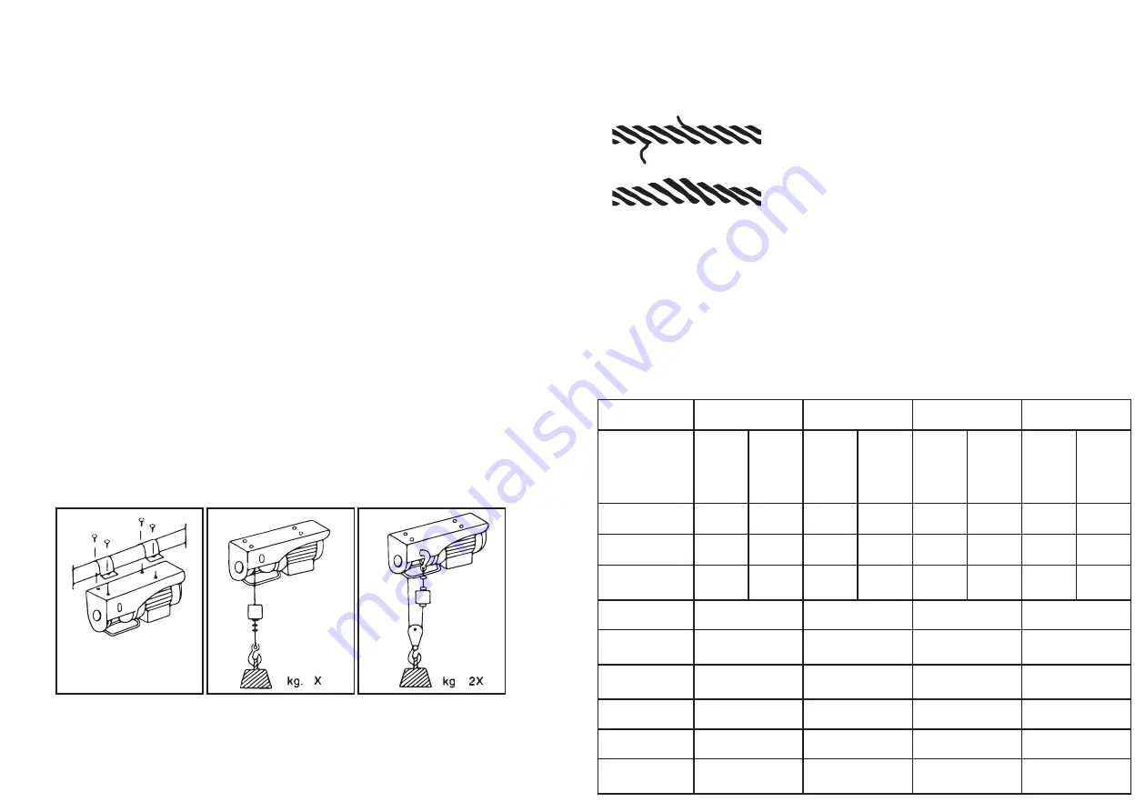
• Periodically CHECK that the steel cable is in
good condition.
• CHECK that the screws securing the brackets
and reduction gear are firmly tightened.
• CHECK THE CONDITION AND TIGHTNESS OF THE
NUTS securin the steel cable clamps.
1
1-2 replace
2
2. INSTALLATION
The hoist “standard version” is fitted with a specially-designed bracket system
that enables it to be bolted to a round, square or rectangular shaped support.
4. TECHNICAL DATA
Model
LH-PA-200G
LH-PA-500G
LH-PA-300G
LH-PA-400G
Standard
version
Version
with
double
load cap
Standard
version
Version
with
double
load cap
Standard
version
Version
with
double
load cap
Standard
version
Version
with
double
load cap
Load capacity 100 kg 200 kg 125 kg 250 kg 150 kg 300 kg 200 kg 400 kg
Lifting height
12 m
6 m
12 m
6 m
12 m
6 m
12 m
6 m
Lifting speed
10m/
min
5m/
min
10m/
min
5m/
min
10m/
min
5m/
min
10m/
min
5m/
min
Cable length
12.5 m
12.5 m
12.5 m
12.5 m
Cable
diameter
3 mm
3 mm
3 mm
4 mm
Cable break
resistance
800 kg
800 kg
800 kg
1200 kg
Service
S3-20%10min
S3-20%10min
S3-20%10min
S3-20%10min
Main voltage
230V~50Hz
230V~50Hz
230V~50Hz
230V~50Hz
Motor
performance
P1=450w
P1=500w
P1=550w
P1=750w
First ensure that outlet specifications (volt-hertz) correspond to those indicated
on the machine plate, and then insert the plug. If a cable extension is required,
it is of utmost importance to comply with the specifications given in the tables.


