background image

Summary of Contents for Corvus Concept

Page 1: ......

Page 2: ...AS WARRANTED ABOVE YOUR SOLE REMEDY SHALL BE REPAIR OR REPLACEMENT AS PROVIDED ABOVE IN NO EVENT WILL CORVUS SYSTEMS BE LIABLE TO YOU FOR ANY DAMAGES INCLUDING ANY LOST PROFITS LOST SAVINGS OR OTHER INCIDENTAL OR CONSEQUENTIAL DAMAGES ARISING OUT OF THE USE OF OR INABILITY TO USE SUCH PRODUCT EVEN IF CORVUS SYSTEMS OR AN AUTHORIZED CORVUS SYSTEMS DEALER HAS BEEN ADVISED OF THE POSSIBILITY OF SUCH ...

Page 3: ... are in increasing order of importance NOTE CAUTION and WARNING The NOTE indicates some action to be taken to speed or simplify a procedure The CAUTION indicates that potential damage to the equipment or user data exists and care should be taken to avoid this The WARNING indicates that potential harm or injury to the service technician or operator exists and extreme care should be taken to avoid t...

Page 4: ......

Page 5: ...CORVUS DEALER SERVICE TABLE OF CONTENTS iii ...

Page 6: ...IDC is a trademark of AC DC Inc Tandon is a trademark of Tandon Corp MACSbug is a trademark of Motorola Corp Synertek is a trademark of Synertek Moss Technology is a trademark of Moss Technologies Inc Rockwell International is a trademark of Rockwell International Corp iv ...

Page 7: ...1 2 Bus Buffers 10 2 1 3 Memory Mapper 10 2 1 4 ROMs and Static RAM 10 2 1 5 OMNINET 11 2 1 6 50 Pin I O Slots 12 2 1 7 Data Communication Ports 13 2 1 8 Interrupts 14 2 1 9 Memory Arbitration 15 2 1 10 Calendar 16 2 1 11 Bell Timer and VIA 16 2 1 12 Data Acknowledge 16 2 2 Concept Mlemory Board 17 2 2 1 Oscillator 17 2 2 2 Horizontal Timing 17 2 2 3 Vertical Timing 18 2 2 4 RAM Timing 18 2 2 5 Me...

Page 8: ...oting 47 5 3 1 Proc ssor Signal Descriptions 47 5 3 2 Processor Test Points 47 5 3 3 Memory and Video Controller Test Points 50 Appendix A Schematics and Assembly Drawings 53 A I Revision 03 Schematics 55 A 2 Revision 04 Schematics 61 A 3 Assembly Drawings 73 Appendix B Troubleshooting Flow Chart 83 Appendix C Test Point Signals 89 C 1 Processor Board Signals 90 C 2 Memory Board Signals 95 Appendi...

Page 9: ... 12 6 Data Acknowledge Timing 16 7 Horizontal Timing Circuit 17 8 Concept Rear View 23 9 Latch Screws 24 10 Electronics Tray Power Connections 24 11 Concept Power Supply Voltage Adjustments 29 12 CRT Adjustment Yoke 31 13 Horizontal and Vertical PCA 31 14 Video PC A 32 15 CORCOM Setting 38 16 Monitor Voltage Test Points 39 17 Rev 03 Boot Switch Settings 43 18 Rev 04 Boot Switch Setting 43 19 Rev 0...

Page 10: ......

Page 11: ...CORVUS DEALER SERVICE CHAPTER 1 OVERVIEW 1 _ _ _ __ _ ...

Page 12: ...assemblies 1111111111111111111111111111111111111 Base Bifurcated Cable Keyboard 1 1 1 Electronics Tray The entire tray may be removed for replacement when an immediate repair is required The Processor Board and Memory Board may be individually substituted if time permits additional troubleshooting 1 1 1 1 Processor Board A MotorolaYM MC68000 Microprocessor Boot RAMs and ROMs OMNINET YM and Clock C...

Page 13: ... of the monitor are IS inch CRT Bit mapped display Vertical tilt of 17 to 13 degrees Horizontal swivel of 90 degrees 720 pixels by 560 pixel screen 120 characters by 56 lines in the landscape mode 90 characters by 72 lines in the portrait mode Software generated character set 1 1 3 Keyboard The compact keyboard is manufactured by Keytronics to Corvus specifications Its features include SelectricTM...

Page 14: ...at Read and write capabilities In addition a 51 4 inch Read Only Disk Drive with a capacity of 140 Kbytes may be purchased from Corvus 1 2 3 Winchester Disk Drive Options Mass storage is provided for the Concept by a line of Winchester Disk Drives Interface to the Concept is through a 50 pin I O slot on the Processor Board The drive models are RevS Model 6 5 7 Mbytes formatted Model 11 10 8 Mbytes...

Page 15: ......

Page 16: ...CORVUS DEALER SERVICE CHAPTER 2 FUNCTIONAL DESCRIPTION 7 ...

Page 17: ......

Page 18: ...upts Memory Arbitration Calendar Bell Timer and VIA Data Acknowledge 2 1 1 Microprocessor The Concept is based on the Motorola MC68000 8MHz microprocessor It has a 16 bit bidirectional data bus a 24 bit address bus and sixteen 32 bit internal registers Its address lines are buffered to go to many locations The 64 pin design eliminates the need for data and address multiplexing by giving each data ...

Page 19: ...e Motorola 16 Bit Microprocessor User s Handbook 2 1 3 Memory Mapper The address space is divided into sections by a memory mapper PROM which examines the state of the address bus and selects the appropriate device M3 12 MEMORY MAPPER 5V M A21 AS 3 A20 N3 A19 6 04 13 NRAMIZl 2 A7 01 9 NROMIZl 13 N3 A12 02 10 NUl NJ 11 10 A16 U309 03 11 NSRAM 825181 05 4 NRAMI A10 12 10 A11 ALTMAP NAS 08 17 NCYCRGM...

Page 20: ...ugh the I O bus The processor places a byte of data on the bus and strobes NOMNI The data consists of three bytes containing an address where OMNINET is to find its command in mem ory The processor checks the Versatile Interface Adapter VIA port A bit 0 to see if the OMNINET is ready to receive another byte of address OMNINET has no other connection with the processor It talks directly to memory p...

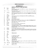
Page 21: ... the processor OMNINET produces 20 address bits Address zero is converted into upper and lower device select before being sent to RAM OMNINET ignores address bits 21 and up 2 1 6 50 Pin I O Slots Four 50 pin board edge connector slots are provided to handle other local I O such as to a Corvus Floppy Disk Drive or Winchester Disk System The I O address space is divided into eight blocks by U605 The...

Page 22: ...0 12V 12V Table 2 I O Slot Pin Descriptions 2 1 7 Data Communication Ports Two RS 232C ports with independent baud rates can be used for an external terminal modem printer or other peripheral device They share the I O bus and interrupt structure with other I O devices The connection is by 10 wire 25 pin sub miniature 0 female shells connected as Data Terminal Equipment A modem eliminator cable is ...

Page 23: ...wn interrupt vectors The data communication control lines shares the lowest vector with the 50 pin bus interrupt Although the processor can be run without interrupts most of the I O devices can cause interrupts so that an effi cient interrupt driven operating system is created Because 6502 I O devices are used which cannot produce vec tors the auto vector mode of interrupt is used The level 7 NMI ...

Page 24: ...in the dynamic memory range 68K RAMSEL is asserted It is then presented to the J input of JK flip flop U204 11 After the Address Select NAS is asserted the Q of the JK flip flop U204 9 will become true at the next 16M clock The Q 68KGO is passed through OR Gate U203 8 to become RAMSEL When the data has been processed by the memory NRAMACK is asserted NRAMACK then goes through an OR gate to become ...

Page 25: ...r floppy drive is to be used as the boot device The orientation switch is needed to indicate whether the screen is to be used horizon tally or vertically Three outputs from the VIA are VIDOFF VAI7 VAI8 VIDOFF must be zero to turn the display on VA17 and VA18 are normally zero for display If they are not zeroed then other than normal areas of memory are displayed 2 1 12 Data Acknowledge The 68000 i...

Page 26: ...tor The oscillator is a self contained crystal oscillator with a frequency of 16 364MHz This frequency is used as the base frequency and is divided to fit system needs 2 2 2 Horizontal Timing A 16 364 MHz oscillator is counted by 2 16 and 512 to produce signals of approximately 8 MHz 1MHz and 32 KHz 32 KHz is the horizontal scanning frequency of the monitor The Processor Board uses the 16MHz 8MHz ...

Page 27: ... load condition Logic high signals are loaded for three clock times assuring that the RAM precharge times are fulfilled A 74LS74 flip flop pair U403 controls MC68000 access to the memory The first flip flop sets following a MC68000 memory request RAMSEL and the 68K signal A memory cycle occurs until NCAS goes high setting the second flip flop and asserting Data Acknowledge NRAMACK Eventually MC680...

Page 28: ...is not reading the buffers are tristate 2 2 10 Video Shift Registers The video data stream requires a data rate of 32 MHz To achieve this 32 bits two words are loaded from 2 banks each microsecond or four words alternate microseconds if four banks are installed The shift register is clocked at 16MHz but is split in two Bits are taken alternately from each half during a clock cycle thus doubling th...

Page 29: ......

Page 30: ...CORVUS DEALER SERVICE CHAPTER 3 DISASSEMBLY 21 ...

Page 31: ......

Page 32: ...fully unpacked and checked for shipping damage External evidence of rough handling may be symptomatic of damage within the Concept NOTE Any damage claims must be reported to the local office of the shipper so an inspection may be made and a damage report filed Also if the damaged equipment is a new product the Corvus Order Processing Depart ment must be contacted for proper return procedures If th...

Page 33: ...ripheral equipment 2 Remove all cables from the back of the base This includes the cable from the monitor from the keyboard tap cable if OMNINET is being used and the power cord Cables to interface cards within the Concept base should be removed when the tray has been opened 3 There are two latch screws on the back of the tray Loosen these screws by turning the left one as you face the back clockw...

Page 34: ...y unscrew the retainer nuts on the latch screws Lift out the Processor Board taking care to disengage the two serial ports from the back panel of the tray 9 Reassemble the tray following the above steps in reverse order Cables should be routed under the speaker tray to prevent interference when replacing the electronics tray 3 6 Power Supply Removal 1 Follow Electronic tray removal steps 1 5 2 Car...

Page 35: ......

Page 36: ...CORVUS DEALER SERVICE CHAPTER 4 ADJUSTMENTS 27 ...

Page 37: ......

Page 38: ...er supply are Digital voltmeter Alignment tool or small screwdriver 1 Follow the Power Supply Removal and Disassembly procedures in steps 1 through 4 of section 3 6 OVAC R32 O COMMON _____ I Figure 11 Concept Power Supply Test Points and Adjustments 2 While measuring the output at one of the Test Points insert an alignment tool into the associated trim pot Adjust to within the tolerance O 10 v R32...

Page 39: ... in a pocket 1 Apply power to the system allowing a minimum of 10 minutes for the monitor to warm up and stabilize 2 Log on to the Concept 3 When the Function Key labels are displayed select the Window Manager function by holding down the com mand key and pressing function key F2 simultaneously A new set of Function Key labels will appear 4 Select the TestPtrn function key by holding down the comm...

Page 40: ... 6 Horizontal Data Centering Select a grid pattern of 4 or 8 Turn the H DATA CENT trim pot RIll see Figure 13 until the grid is cen tered within the raster A poorly aligned screen may exhibit fold over L102 R179 Figure 13 Horizontal and Vertical PCA 31 ...

Page 41: ...at the grid is centered Using a plastic trim tool adjust L101 see Figure 13 until the horizontal width measures 10 5 inches 27 centimeters Use the center line of the grid for measurements It may be nec essary to repeat Steps 5 and 6 9 Brightness Tum the Brightness Limit trim pot R179 see Figure 13 until the raster is just visible Turn the Brightness knob on the rear of the monitor through the enti...

Page 42: ...t line should be parallel to the edge of the metal frame around the CRT and at a distance of 2 375 to 2 5 inches 6 to 6 4 centimeters If the line is paralld but the distance is incorrect readjust the Vertical Centering trim pot If the grid is centered but the leftmost line is not parallel the CRT must be rotated inside the frame 13 Focus To adjust the focus select a pixel pattern With the raster j...

Page 43: ......

Page 44: ... _ _ _ _ __ CORVUS DEALER SERVICE CHAPTERS TROUBLESHOOTING 35 ...

Page 45: ......

Page 46: ...equired to repeat the failure For example If the monitor has no raster it would be safe to eliminate the floppy drive from the system Note that if the symptoms disappear after removing a cer tain section that section may be the problem area Do not remove peripherals needed to run the diagnostic tests The third step is to substitute a suspect module with a known good module If the problem disappear...

Page 47: ...e seating of internal plugs and connectors During shipment they may work loose 4 Remove the four screws that hold the back panel in place Locate the low voltage PCA at the bottom of the unit Check for proper voltage at Test Points 301 and 302 See Figure 16 38 ...

Page 48: ... 1 If the DC voltages are not present check to see if the muffin fan is turning This indicates that the line voltage is present If the fan does not turn check the primary windings of the transformer with an AC voltmeter See Figure 11 This voltage should be equal to the line voltage 2 If there is no primary voltage check the fuse link If the fuse link is good check the continuity of the on off swit...

Page 49: ...ing bus error and sending bell characters on Data Com ports A serious problem may prevent some or all of these actions If there is no error the processor will perform a checksum on the ROM and write and verify an incrementing pattern in the static RAM If these tests are successful system variables are written into the static RAM Next the UARTS baud rates parity etc are set up to default conditions...

Page 50: ...will not specify which UART is bad Level 2 troubleshooting will be neces sary to find the defective UART using a MACSbug routine See Level 2 Troubleshooting in Section 5 2 If you do not have Level 2 capabilities replace the Processor Board from your spares kit Refer to Section 3 5 of this manual for Disassembly and Assembly instructions 2 Test 2 failure indicates that an invalid code was detected ...

Page 51: ...ocedures do not remedy the problem Level 2 troubleshooting will be required If you do not have Level 2 capabilities replace the Processor Board Refer to Section 3 5 of this manual for Dis assembly and Assembly instructions 7 Test 7 Test 7 will verify that the OMNINET host number is unique This routine will store the host number into data register DO A WHO command is then sent across the network ch...

Page 52: ... CORVUS DEALER SERVICE OFF ON DI D 12 SiS Figure 17 Rev 03 Boot Switch Settings OFF ON ols 10 17 Figure 18 Rev 04 Boot Switch Settings 43 ...

Page 53: ...stallation try to reboot from the Floppy Disk Drive If it stills fails refer to the Floppy Drive Service Manual for Level 2 floppy drive service procedures 5 2 Level 2 Troubleshooting This level of troubleshooting is recommended for in depth troubleshooting of the Processor Board and Memory Board It requires a knowledge of digital troubleshooting techniques and an understanding of assembly languag...

Page 54: ...6 PIace the ROM labeled MACSbug 2 0 L in location U709 Place the ROM labeled MACSbug 2 0 H in location U708 of the Processor Board The MACSbug ROM sockets are 28 pin sockets and the MACSbug ROMs are 24 pin devices The sockets should have the top four pin locations unused i e pins 1 2 27 and 28 Figure 19 depicts proper installation Revision 04 and later 4 Locate the Boot ROMs on the Processor Board...

Page 55: ...ocedure until the system boots If problems persist contact Corvus Customer Service 5 2 2 Communicating with MACSbug Communication with MACSbug is performed through the two serial ports on the back of the Corvus Concept When used with MACSbug Port 1 has a default data rate of 9600 baud parity is disabled and an 8 bit character size is assumed An ASCII terminal must be attached to Port 1 with a null...

Page 56: ...cessor Board consists of many layers Damage will occur to the board if proper soldering procedures are not followed 5 3 1 Processor Signal Descriptions A few major signals should be tested before checking the Test Points The Concept will not operate unless these signals are present 1 Clock Signals If clock signals are incorrect or absent a bad buffer IC UI09 74LS04 may be present If the inputs of ...

Page 57: ...f asserted OMNINET has total control over the memory address and data bus If the processor attempts to access memory it will go into a wait state until the DMA operation is complete 2 Test Point 2 DMAEN When the DMAREQ is asserted it is latched into a JK flip flop on the next 16M clock pulse The output of this latch is the signal DMAEN 3 Test Point 3 8M The 8M signal is the system clock This clock...

Page 58: ... Point 13 NOMINT The Concept processor recognizes seven levels of interrupts OMNINET utilizes a level three interrupt The OMNINET 6801 will generate an interrupt to the 68000 when a transaction is complete or when an error is encountered 14 Test Point 14 HALT HALT is a bidirectional signal that can be asserted either by the processor or by external software When this signal is asserted low all con...

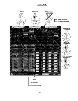
Page 59: ... horizontal and vertical blanking pulses Some key signals are described in the follow ing paragraphs See Table 5 for actual signal locations and Appendix C 2 for Test Point locations 1 16M Signal Name 16M HSYNC VSYNC ENVID LOADVID NVIDTIME MUX NRASTIME NCASTIME 68K NWL NWU Board Location U101 1 U105 4 U105 2 U301 15 U504 2 U401 7 U405 14 U405 15 U405 13 U305 3 U305 3 11 Table 5 Memory and Timing S...

Page 60: ... time must be con sistent and accurate Z NMUX During NVIDTIME the video address counter is selected to address the memory The signal NMUX deter mines whether the upper or lower part of the address goes to the memory to be stored by RAS and CAS The signal NRASTIME is derived from the horizontal counter It is used in conjunction with the Bank Select to create the Row Address Select RAS for the vario...

Page 61: ......

Page 62: ...CORVUS DEALER SERVICE APPENDIX A SCHEMATICS AND ASSEMBLY DRAWINGS 53 ...

Page 63: ...D COMM I 1 I j I I I I I I VIA 5V 5V 5V NEXTASSY USED ON APPlICATION 3 I NRESEf I R2J1k R l_ IK R1Z IK UNLESS OTHERWISE SPECIFIED DIMEN6IOMS ARE IN INCItES TOLERANCES ON ANGLES DECIMALS t XX t 4 REVISIONS PCO REV DESCRIPTION DATE APPAO EO 43 REt oOR PR O TII _ _ 1 _ _ _ _ _ _ion_II no lIe _ yorlnCllroctly __ _ta _01 COIMIIt 1 SYSTEM8 ____ __ SIz DATU NOv CHCCIWIa D ICALE 55 CORVa5 S S1BWIS SPKR 5 ...

Page 64: ... Ir 11 03 OS J iVel 68KRA14 I A4 NWRITEX A 8 0 flO c 1M 4 14 15 a Q lJ2 75 0 2 3 4 REVISIONS I 57 ...

Page 65: ... X DI _4 1Q D 5 501 i V02 7 Q D SDt XD Q DI 5 ll DI _I Q 12 504 I XD5 14 Q D 15 5D5 f XDb 17 Q D 10 S XD7 18 Q 0 19 5D7 1 1 IS 5D Ig D 1 SAle I 1t4 IS I 505 f sD4 18 D4 QU ID U5rJt J e 2 JVJI 1 so s 17 DS SAI1 I 283 AI II Q 175 D 12 sOA S 10 D el f SD7 IS D7 SAIii 4 1 _ L l7Q I 5 ____ 5 D 3________ eijI ON 7 7 9 LU IN ou 4 U7 4 UNLESS OTHERWISE SPECIFIED DIMENSIONS ARE IN INCHES TOLERANCES ON ThiS...

Page 66: ...ADS lNDICATE5 TRANSisTOR 2 5QUA CJl P EMITTER TIFY REV LE VEl END MARK OR IOEN PERMANENTLYHERE SHOWN APPROX W NOTES lSE SPEClFIED UNLE55 OTHE RW REV 03 FC B CORV JS 9 lI 1 31 9010IIII EV U5 CONC 6 B PROCE550__ R_Ba ___ I l w C fII J1 t In G 8010 08024 MATERIAL 61 ...

Page 67: ... 52 A2 3 68Ne 8 MHz 6 2 MEMORY 1 KEYBOARD COMM NEXT ISSY USEOON APOUCATION UNLESS OTHERWISE SPECIFIED DIMENSIONS ARE IN INCHES TOLERANCES ON 4 REVISIONS PCO REV DESCRIPTION 01 PRE PFtOD 02 U314 COfwN I Xc TSI DA TE A PPROVED ex w t z ci 4 a W U A 4 8 SPKR OOR VYS CONCEPT PROCESSOR 5V VlDON VAI7 VAIS REV SHEET I OF 3 l r 63 ...

Page 68: ...2 3 65 4 REVISIONS DESCRIPTION DATE IAPPROVED CORVUS COnCEPT PROCESSOR I I REV 04 A B c ...

Page 69: ... 3 J 5 IZ H6 __ OWER SUPPLY DECOUPlING v MDNOCHIP UI 9 OT ALL TTL DEVICES ARE 74LSXX UNLESS OTHERW SE NOTED 8 4 7t2V J8 3 5V C 14z F 47pF F 0 I F PER 5 LS DEVICf S I on l 4iJ TCSg C6 r 0 I cJt FOR EVERY OEV cE GREATER THAN v OR EQUAL TO 20 PIN t _ 2 J1 01 4 8 1 MIDDLE PIN 20 D2 _ J C59 If F U4 SOl SDl 19 D3 5V Ul13 5V r _____ a t 1 3 A NIf J _ I jeD4 4 16 I SHIELD I 17 D5 RXD 3 3 r I I U 11l1A I 2...

Page 70: ...GD Cl ILY LM CHt IW mJLY CHN D ITEM 55 rLM 1 BOOT PROM UlU IJ 1LM ADD ITEM 18 Rij3 f WK INSTR CHN G b DNLY O l 5 SEE PCD i fiJO iiNGoD 00 TO 47u HKldl RN3 10 RP3 UPDIIT CD k BlDO Q ADD ITEM 9 elM R REL OF REv 8 PC B B 9 BZ O2 ID b 82 ID Il Sf 10 4 81 I I 82 IO Z5 Bl 11 12 1 Z 1I IZ 82 r1 I1 l 132 2 8 2 18 13 2 18 83 3 11 3 UNlfSS OTHERWISE SPECIAED DIMENSIONS ARE ININCHES TOLERANCES ON TlIIa _ _ y...

Page 71: ... VIDEO ADDRESS COUNTER ADDRESS MULTIPLEXING HORIZONTAL TMNG VERTICAL TIMING RAM TIMING 71 REVISIONS IPCO IRE J DESCRIPTION I DATE IAPPROVED J6 t 2 AJ 2 J ...

Page 72: ......

Page 73: ...1 lkl J 1 kl I 4 111 1 I I I A 2 3 2 2 009 2 QQ g UNLESS OTHERWISE SPECtRED t r t DIMENSIONS ARE IN INCHES TOlERANCESON 4 2 2 2 DOB DOC DOD DOE ThI _ _ _ In ondlo _ _ _ c ardIIan _ It wIIl_ ba _ ar _ 5V I S16 a V 0 rQ IIf Z CORVUS SYS J 8It1S 2029aTooIe_s Ja CA I5131 J I ANGUS DECIMAlS ta _otOOIMIS I R EV t z xx 1 D ru Il70ECei CORVUS CONCEPT A TI I I L Ir_ M I _ _COO K M E M O R Y 4481 A I sEE sH...

Page 74: ...SIONS PCO REV DESCRIPTION DATE APPROVED 1 1Ll A r tL rUK FROD 7 3 575 B A17D REWORK ItJST S h P 7 C CHG 11Etvl 26 a 26Jj2 7r 3 D A DD ITEM s TO LIM 10 ll B2 771 CWG TOL RANt ON UTO L ft 1I le s 2 91 F ADO ITEM 44 LLM 2 18 8 f vH TllIl document Conlalna prOl nel ry tnlormaUon and II Gell eCI UPQf1 the eapreued c onchtion II wHI not uNCI dWeclly or 6ndnctty 111 any lolhOln_O CORVUS t t CORVUS SYSTEM...

Page 75: ...ESS OTHERWISE SPECIFIED DIMENSIONS ARE IN INCtfES TOlERANCES ON ANGLES DECIMALS xx t XXX t MATERIAL FINISH REL R PR o pCo RB DEsc RIPTloN CORVUS SYSTI MS _ aJ29 OT_ s CA 95131 _10__01 COIWUII SYSTEMS 79 CORVUS CONCEPT MONITOR ASSY DWG SHEET I OF ...

Page 76: ...IED DIMENSIONS ARE IN INCHES TOLEAANCES ON ANGLES I IECIMAU XX XXX 1 REVISIONS DESCRIPTION DATE APPROVED Rt L FOR PROD NCTfE JLOCAT IN BASE PER R c SSED AREAS Thla n cantaJno 1n_1On _ _ _ _ _ __ M _1IIrectIy In _ _ 1D _efCOAV ll SYSTEMS I DAVt 1U CHiCIIIiDIY 81 CORVUS SYS1 EMS 2D2IOT___ SonJme CAZI31 CORVUS CONCEPT BA5E 25 K DOME5T C SHEET I Of I ...

Page 77: ......

Page 78: ...CORVUS DEALER SERVICE APPENDIXB TROUBLESHOOTING FLOW CHART 83 ...

Page 79: ... 5 NO REPLACE MEMORY BOARD SEC 3 5 I LEVEL ONE TROUBLESHOOTING FLOW CHART KEY YES BOARD YES RESPONDS OK NO YES CHECK YES KEYBOARD INSTALLATION NO YES CLEAN KEYBOARD YES SEC 3 4 NO YES REPLACE YES KEYBOARD YES I I ALL BOOT SYSTEMS TESTS PASS I NO SYSTEM YES NO CHECK TEST 1 BOOT YES OK SWITCHES FIG 17 18 NO SYSTEM TEST 2 YES INITIALIZE SYSTEM NO OK SUBSTITUTE YES KNOWN GOOD BOOT SYSTEM NO SYSTEM YES...

Page 80: ......

Page 81: ...This page intentionally left blank ...

Page 82: ......

Page 83: ...CORVUS DEALER SERVICE APPENDIX C l PROCESSOR BOARD TEST POINT SIGNALS 89 ...

Page 84: ......

Page 85: ...I L IL 10 J o j t j o I 2V DIV 1 us TP 14 HALT I 100 o J If I J J l 10 f o o I I o l o I 2V DIV 2 us TP 17 IPL2 lOp 90 J I t J J l 10 I I l 2V DIV 10 ms TP 20 NDTACK I 1O 90 I o I I o l 10 t J f l l 0 I 2VIDIV 5 us TP 23 NKBD I 10 0 90 1O o I 2V OIV 1 ms 91 TP 15 NWRITE I __ _ H IJO o f o I 1 10 r 2V DIV 2 us TP 18 IPLO J 10 0 M I D _ _ o 2V DIV 10 ms TP 21 NSRO I lOp 901 o i f I f i l r r u u J _...

Page 86: ...92 ...

Page 87: ... 1 r 10 l I l 4 o J o I 2V DIV 2 us TP 5 IN OUT I 10 0 90 I II I I 11 1 1 TT irl 10 O I 2V DIV 2 us TP 8 NCS I 10 0 90 11111111 11111111 1 1 11 111 11111 10 07 I 2V OIV 5 ms TP11 NAS I 10 0 90 f _ _ J J _ __ I __ L _ 10 l I J l 4 t o o l l o I 2V OIV 5 us 93 TP 3 8M l 1 10 0 901 f f_ j_ _ _ j 1 I 1 if I J J 1 l 10 ___ _ f__ t I 2V DIV 05 us TP 6 NTACK I 1 0 I 90 i H f t4 IIi It HII I fl I l ID _ 1...

Page 88: ......

Page 89: ...CORVUS DEALER SERVICE APPENDIX 2 MEMORY BOARD TEST POINT SIGNALS 95 ...

Page 90: ... 2V DIVD 10 us MTP 5 LOADVID I IJO O f o l i II II I j l rl fl II 10 t t t t I o I 2V DIV 10 us MTP 8 NRASTIME I 10 0 90 t l n n 1 1 L L L L 10 t r t i o I 2V DIV 5 us MTP 11 N10L I Ido O f o r t I r r If IJ U u 10 t l f f I f l I 2V DIV 96 2 us MTP 3 VSYNC I I O 90 i J r I I 10 f o r I o I 2V DIV 5ms MTP 6 NVIDTIME I I O 0 90 1 1 I Ir IC l J L J il J L 10 or 0 I 2V DIV 5 us MTP 9 NLASTIME I lOp 9...

Page 91: ...97 ...

Page 92: ......

Page 93: ...CORVUS DEALER SERVICE APPENDIXD TIMING CHARTS 99 ...

Page 94: ......

Page 95: ... recommended that backups be made of the diagnostic floppy In instances where the 50 pin 110 slots are defective a copy on a network system will be helpful The following steps are to indicate timing relationships between key signals and not their waveshapes 0 1 Processor Timing Setup MACSbug Option OM 80000 External Clock 16 MHz Trigger NAS UI03 2 Processor Timing Diagrams Ao 8MHz UI03 6 Al NWRITE...

Page 96: ...al Drive Boot Setup Boot Local Drive External Clock 1 Mz Trigger NIO Local Drive Boot Timing Diagram Ao NIO U60S 44 Al 10 U604 33 A2 lOGO U604 S A3 IOACK U60S 3 102 A4 NEVS U60S IS AS NI02 U60S I3 A6 NDEV2 U704 I3 A7 NIOSTB U70S 7 ...

Page 97: ... Setup 0 Test Option Send Set External Clock 16 Mz Trigger NOMNI 3rd pass Omninet Timing Diagram AO NOMNI UI09 32 Al READY UI09 311 A2 DMAREQ UI09 34 A3 DMAEN UI04 5 103 A4 DMAG02 UI04 9 A5 RAMSEL U203 8 A6 68KRAMSEL U205 5 A7 NRAMACK U205 11 ...

Page 98: ...n Question External Clock 16 Mz Trigger LATCHRAM Ram Access Timing Diagram Ao 68K MU401 12 Al NVIDTIME MU401 7 A2 ENVID MU301 1S A3 LOADVIO MUS04 2 A4 MUX MU40S 14 AS NRASTIME MU40S 1S 104 A6 NCASTIME MU40S 13 A7 LATCHRAM MU20S 4 Bo NWU MU30S 3 Bl NWL MU30S 11 B2 RAMSEL MU604 9 B3 NRAMACK MUS04 4 ...

Page 99: ...This page intentionally left blank ...

Page 100: ......

Page 101: ...CORVUS DEALER SERVICE APPENDIX E l MACSBUG COMMANDS 107 _ _ _ ...

Page 102: ......

Page 103: ...M 80000 80000 OF SA AA 22 00 11 00 00 00 00 00 00 00 00 00 00 These two commands will aid in diagnosing a memory failure For example bank 1 2S6k bank 1 bank 3 S12k 80000 OF SA AA 220011 00000000000000000000 bank 0 bank 2 S12K bank 0 2S6K Each bank can then be divided into upper and lower bytes OF SA upper byte The byte can then be further divided into eight bits lower byte o 0000 it F F 1111 bit 8...

Page 104: ......

Page 105: ...CORVUS DEALER SERVICE APPENDIX E 2 MACSBUG ROUTINES 111 ...

Page 106: ......

Page 107: ...080 13 testlx move dO aO moves ffff into 80000 0018 60FC 14 bra s testlx 15 16 TEST TWO AND THREE SAME AS TEST ZERO AND ONE BUT 17 FOR BANK ONE 18 TEST TWO LOAD ZERO FOREVER AT LOCATION 80002 001A 207C 0008 0002 19 test2 move 1 80002 aO 0020 4280 20 elr 1 dO 0022 3080 21 test2x move w dO aO moves zeros into 80002 0024 60FC 22 bra s test2x 23 24 TEST THREE LOAD ZERO FOREVER AT LOCATION 80002 0026 2...

Page 108: ...0008 0002 64 test9 move 1 80002 aO 0076 4280 65 elr l dO 0078 3080 66 test9x move W dO aO 007A 3210 67 move W aO dl 007C 60FA 68 bra s test9x 69 70 TEST TEN FILLS RAM WITH AN INCREMENTING PATTERN 007E 207C 0008 0000 71 testlO move 1 80000 aO 0084 30CO 72 testlOx move dO aO 0086 5240 73 addq 1 dO 0088 60FA 74 bra s testlOx 75 76 TEST ELEVEN SEND DATACOMM ZERO 00030F21 77 ddataO equ 30f21 00030F23 7...

Page 109: ...e s testl2x OOCE 13CO 0003 OF41 104 move b dO ddatal 1 0004 60EE 105 bra s testl2x 106 end COMMDO OOOOOOAB DDATAO 00030F21 TEST10X 000084 COMMDI OOOOOOAB DDATA1 00030F41 TEST11 00008A CONTRO 00000037 DSTATO 00030F23 TEST11X 00009E CONTR1 00000037 DSTAT1 00030F43 TEST12 OOOOBO DCOMMO 00030F25 TESTO 000000 TEST12X 0000C4 DCOMMI 00030F45 TESTOX 000008 TEST1X 000016 OCONTO 00030F27 TEST1 OOOOOC TEST2 ...

Page 110: ......

Page 111: ...CORVUS DEALER SERVICE APPENDIX E 3 SELF TEST ROUTINES 117 ...

Page 112: ......

Page 113: ... max bsr trapp jumps out to MACSbug 0008 207C 0000 0700 17 Ramtstl move 1 srambeg aO OOOE 6100 006E 18 bsr walkbit 0012 660C 19 bne s rtlerr 0014 227C 0000 OFOO 20 move 1 sramend a1 001A 6100 0094 21 bsr march 001E 670A 22 beq s ramtst2 0020 2C3C 0000 0001 23 rtlerr move 1 0001 d6 0026 6100 010E 24 bsr trapp 25 002A 207C 0008 EOOO 26 ramtst2 move 1 dspend aO 0030 6100 004C 27 bsr walkbit 0034 660A...

Page 114: ...AE 4E75 66 wberr rts 67 OOBO 2448 68 march move 1 aO a2 00B2 4280 69 elr 1 dO 00B4 34CO 70 mr1 move w dO a2 00B6 B5C9 71 cmpa l a1 a2 00B8 66FA 72 bne s mr1 OOBA 3400 73 move w dO d2 OOBC 4642 74 not w d2 OOBE 3222 75 mr2 move w a2 d1 OOCO B240 76 cmp w dO d1 00C2 6616 77 bne s mrerr 00C4 3482 78 move w d2 a2 00C6 B5C8 79 cmpa 1 aO a2 00C8 66F4 80 bne s mr2 OOCA 3002 81 move w d2 dO OOCC 4642 82 n...

Page 115: ...r 1 aO 0128 B1C9 115 cmpa 1 a1 aO 012A 6FFA 116 ble s zeroram 012C BABC 0000 0001 117 cmp 1 01 d5 0132 6702 118 beq s trapp 0134 4E75 119 rts 0136 4E4F 120 trapp trap 15 0138 0000 121 data w 0 013A 4E75 122 rts 00000004 123 end max DSPBASE 00080000 MAX 000004 RAMSIZ1 00010A DSPEND 0008EOOO MEMCLR 00005A RAMSIZ9 000124 DSPLEN OOOOEOOO MEMTEST 00004A RAMSIZE OOOOFC INCTEST OOOODC MR1 0000B4 RAMTST1 ...

Page 116: ......

Page 117: ...CORVUS DEALER SERVICE APPENDIX F l GENERAL MEMORY AND I O MAPS 123 ...

Page 118: ......

Page 119: ...X addresses must be odd DEVS I O slot registers 0300xx 0301xx 101 102 103 ROM ROM ROM 104 ROM SLOT STAT 302xx 304xx 306xx 308 30Axx 303xx 305xx 307xx 309xx 30Bxx CALENDAR R W 030Cxx 030Dxx I O PORTS RS232 Keys Etc 030Exx 030Fxx r see I O ROM equivalences below SLOT o NNMI 1 1 NNMI 2 2 NNMI 3 3 NNMI 4 4 NIRQ 1 5 NIRQ 2 6 NIRQ 3 7 NIRQ 4 b iT __ ____ ____ ____ __ ____ ____ ____ L ____ __ When an I O...

Page 120: ......

Page 121: ...CORVUS DEALER SERVICE APPENDIX F 2 ROM MAPPING OF I O SLOTS 127 ...

Page 122: ......

Page 123: ...0205 C102 30207 C103 1 303FF C1FF 30401 C200 I 30403 C201 2 305FF C2FF 30601 C300 3 307FF C3FF 30801 C400 4 309FF C4FF I 39FE1 CFFO IOSTRB 39FFF CFFF IOSTRB is only available in 16 locations Note that the 6502 code will not execute on a 68000 However the ROM ID and various tables may be useful Drivers must be written in 68000 code and included in the operating system or attached using the INSTALL ...

Page 124: ......

Page 125: ...CORVUS DEALER SERVICE APPENDIX F 3 VIA GENERAL PURPOSE I O PORT SYNERTEK 6522 131 ...

Page 126: ......

Page 127: ...put register A Input register A no handshake Port A DDRA 30F67 to preset to 80 ORA 30F7F to read write 0 Ready OMNINET Input 1 Clear to send DCO Input 2 Clear to send DCl Input 3 Dataset ready DCO Input 4 Dataset ready DC1 Input 5 Data carrier detect DCO Input 6 Data carrier detect DCl Input 7 lOX exclusive OR of above signals for interrupt Output Port B DDRB 30F65 preset to 37 ORB 30F61 to read w...

Page 128: ......

Page 129: ... _ CORVUS DEALER SERVICE APPENDIX F 4 OMNINET 135 ...

Page 130: ......

Page 131: ... 30FAl 30FBF 30FCl 30FDF CORVUS DEALER SERVICE APPENDIX F 4 OMNINET Transporter register Reset OMNINET interrupt For OMNINET operation refer to the OMNlNET user s guide 137 ...

Page 132: ......

Page 133: ...CORVUS DEALER SERVICE APPENDIX F 5 CLOCK CALENDAR ALTMAP VOLUME 139 ...

Page 134: ......

Page 135: ...ewritten with the chip enable O Thirdly the register read or write is performed at address 030C01 Finally 10 is written to 030F81 to deselect the chip The data to or from the chip is on bits 0 to 3 Bit 5 is the volume control for the bell A zero must be written to bit whenever this register is written to except when a quiet bell is sound When the quiet bell has stopped sounding a zero must again b...

Page 136: ......

Page 137: ...CORVUS DEALER SERVICE APPENDIX F 6 DATA COMMUNICATION AND KEYBOARD REGISTERS 143 ...

Page 138: ......

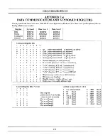
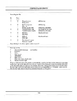
Page 139: ... 1 x x x x Echo mode received data is retransmitted x x x x 0 0 x x Tx INT disabled RTS off Transmitter off x x x x 0 1 x x Tx INT enabled RTS on Transmitter on x x x x 1 0 x x Tx INT disabled RTS on Transmitter on x x x x 1 1 x x Tx INT disabled RTS on Transmit BREAK x x x x x x 0 x IRQ interrupt enabled from bit 3 of status x x x x x x 1 x IRQ interrupt disabled x x x x x x x 0 Disable receiver ...

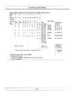
Page 140: ...us bit 2 Interrupt priority 7 6 5 4 3 2 Non maskable interrupt Keyboard Timer Data ComO OMNINET Data Com 1 not installed 1 Data Com control Apple slots o Normal no interrupt When an interrupt occurs the priority is automatically raised to the level of that interrupt preventing further interrupts of the same priority or below A return from interrupt restores the priority at the time of the interrup...

Page 141: ...X X 0 1 0 0 0 0 Here X is 0 or 1 all other locations should be programmed to 7E Board level testers may jumper WRITE this pin instead of A22 HEX ADDRESS 000 100 000 100 200 300 020 120 220 320 010 110 210 310 030 130 230 330 X04 X14 X24 X34 X84 X94 XA4 XB4 Here x can be 0 1 2 3 This pin is ALTMAP It should always be zero for Concept It can be jumpered 147 RESOURCE RaMO RaMO SRAM RaMO RaMI I O DRAM...

Page 142: ......

Page 143: ...CORVUS DEALER SERVICE APPENDIXG MEMORY BOARD JUMPER LAYOUT 149 ...

Page 144: ......

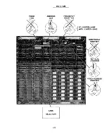
Page 145: ...VIDEO TIME ADDRESS MUX BANK SELECTION 151 256 K RAM FREQUENCY SELECTION NO JUMPER 60HZ WITH JUMPER 50HZ ...

Page 146: ...VIDEO TIME ADDRESS MUX BANK SELECTION 512 K RAM 152 FREQUENCY SELECTION NO JUMPER 60HZ WITH JUMPER 50HZ ...

Page 147: ...CORVUS DEALER SERVICE APPENDIXH CONNECTOR 153 ...

Page 148: ......

Page 149: ...nterrupt line DMA daisy chain could be used for 10 card priority DMA is NOT IMPLEMENTED 500mA total current is available for all I O cards System Electric Ground Daisy chained DMA DMA is not implemented Daisy chained interrupt priority in Non Maskable Interrupt X When the MC68000 interrupt priority is zero a zero on this line will cause an interrupt The source of the interrupt can then be determin...

Page 150: ......

Page 151: ...CORVUS DEALER SERVICE APPENDIX H 2 DATA COMMUNICATION PORTS J1 AND J2 157 ...

Page 152: ......

Page 153: ...tive Ground 2 103 BA Transmitted Data 3 104 BB Received Data 4 105 CA Request to Send 5 106 CB Clear To Send 6 107 CC Data Set Ready 7 102 AB Signal Ground 8 109 CF Data Carrier Detect 20 108 CD Data Terminal Ready 23 111 CH Data Signal Rate select high low Baud Rate dual speed modems All other pins are open 159 ...

Page 154: ......

Page 155: ...CORVUS DEALER SERVICE APPENDIX 3 BOARD CONNECTORS J4 JS AND J6 161 ...

Page 156: ......

Page 157: ... Gnd Gnd 10 RA13 DOB NRAM1 11 SV SV RA21 12 RA12 AOB RA20 13 Gnd Gnd Gnd 14 RAIl 009 RA19 15 SV SV RA22 16 RA10 D08 NRAMACK 17 Gnd Gnd Gnd 18 RA9 D07 RAMSEL 19 SV SV SV 20 RA8 D06 VA17 21 Gnd Gnd Gnd 22 RA7 DOS VAl8 23 SV SV SV 24 RA6 D04 VIDOFF 25 Gnd Gnd Gnd 26 RA5 D03 RNLDS 27 SV SV SV 28 RA4 D02 NWRITEX 29 Gnd Gnd Gnd 30 RA3 DOl NPARITYSELECT 31 SV SV 5V 32 RA2 DOO XNRESET 33 Gnd Gnd Gnd 34 RA...

Page 158: ......

Page 159: ...CORVUS DEALER SERVICE APPENDIX H 4 ADDITIONAL CONNECTORS 165 ...

Page 160: ......

Page 161: ...ines between 0 and 5V Speaker and Battery Connector JS Pin Description 1 Speaker 2 5V 3 Battery 4 Gnd PCA Power Connector J8 Pin Description 1 Shield 2 Ground 3 5V 4 12V 5 12V 6 Open Keyboard and Orientation Switch Connector J9 Pin Description 1 Ground 2 Orientation switch 3 Keyboard data out 4 5V 5 Keyboard data in 6 Ground 7 Open 8 Shield _ _ _ _ _ _ 167 ...

Page 162: ......

Page 163: ...CORVUS DEALER SERVICE APPENDIX I CONCEPT PARTS LIST 169 ...

Page 164: ......

Page 165: ... 21 2 LOCKWASHER 6 HEX ALLEN 6 32 X 1 2 HEX ALLEN 6 32 X 3fs ALLEN 8 32 X 1 2 ALLEN 10 32 X 1 4 STANDOFF 6 32 RIGHT GRIPLATCH LEFT GRIPLATCH SERVICE MANUAL CONCEPT ADMINISTRATION MANUAL SERVICE DISKETTE CONCEPT BINDER DEALER REPAIR TAGS 171 PART NO 8010 08082 8010 08083 8010 08670 8010 08024 8010 08051 8010 08546 8010 08522 6010 02007 8010 08091 8010 08520 4000 02982 8010 08523 3100 01881 3100 018...

Page 166: ......

Page 167: ...CORVUS DEALER SERVICE APPENDIX SPECIFICATIONS 173 ...

Page 168: ......

Page 169: ...racter Set Keyboard 91 Key Detached Keyboard Selectric R Style Keyboard 1 5 Keyboard Numeric Keypad 10 Programmable Function Keys Cursor Control Keys Operating Systems and Software UCSD Pascal File Structure ISO Pascal with UCSD Extensions Native Code Compiler FORTRAN 77 Native Code Compiler 68000 Assembler EdWord Word Processor LogiCalc Electronic Spread Sheet CP M Compatability Electrical Specif...

Reviews: