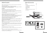
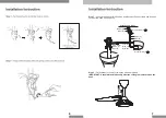
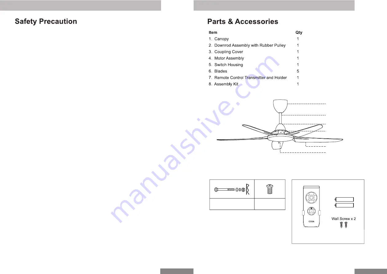
Canopy
Downrod
Coupling Cover
Motor Assembly
Blade
Switch Housing
33
DO NOT pull out the power cord when the power is ON. This may cause serious electrical shocks
which may result in fire hazards.
STOP using the ceiling fan when any abnormality or failure occurs.
If unusual oscillating movement is observed, immediately stop using the ceiling fan and contact the
manufacturer, its service agent or suitably qualified persons.
CAUTION
Please take note of the following important points when installing.
The fixing means for attachment to the ceiling such as hooks or other devices shall be fixed with a
sufficient strength to withstand 4 times the weight of the ceiling fan.
The mounting of the suspension system shall be performed by the manufacturer, its service agent or
suitably qualified persons.
The fan is to be installed so that the blades are more than 2.5m above the floor.
Safety cord should not be longer than the earthing conductor.
Should failure of the suspension system occur, the supporting of the fan must not rely on the earthing
conductor. The earthing terminal in the fan assembly should be such that should any part of the
suspension system fall off, the body of the fan assembly shall effectively earthed.
Ensure that the unit’s panel is closed after service or installation.
Unsecured panels will cause the unit to operate noisily.
Sharp edges and coil surfaces are potential locations which may cause injury hazards. Avoid
from being in contact with these places.
Before turning off the power supply set the remote controller’s ON/OFF switch to the “OFF”
position.
If this is not done, the unit’s fans will start turning automatically when power resumes, posing a
hazard to service personnel or the user.
Do not operate any heating apparatus too close to the ceiling fan unit or use in room where mineral
oil, oil vapour or oil steam exist, this may cause plastic part to melt or deform as a result of excessive
heat or chemical reaction.
Ensure the colour of wires of the outdoor unit and the terminal markings are same to the indoors
respectively.
Don’t use joined and twisted wires for incoming power supply.
Do not place any object in the path of the blades. Avoid raising objects or your arms near the ceiling
fan.
The fan suspension system and blade screw tightening shall be examined yearly.
Replacement of parts of the safety suspension system device shall be performed by the manufactur-
er, its service agent or suitably qualified persons.
2
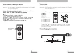
Transmitter Kit
Transmitter &
Holder x 1
AAA
AAA
Battery x 2
Blade Holder
Screw x 11
Bolt x 2
Assembly Kit
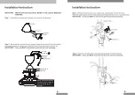
FAN OFF
2
1
3
4
6H
1H
3H


