background image


-22-

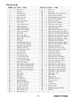
Parts List    

ITEM 

Q’TY PART  NAME 

ITEM Q’TY PART  NAME 

1 Main 

Frame 

47 

1 Tail 

Cover 


1 Seat 

Post 


48 

1 Top 

Cover 


Seat Post Slider 


49 

8x38mm Hex Head Screw Black   

1 Front 

Handlebar 

50 

TP 3x8mm Screw (Black)


1 Front 

Foot 

Tube 


51 

TP M3x20mm Screw (Silver) 


1 Rear 

Foot 

Tube 


52 

M6x 40mm Screw(Black)   

1 Belt 

Tension 

Bracket 


53 

TP 4 x 12mm (Silver)   

1 Console 

Tube 


54 

28  TP 4x16mm Screw (Black)   

ψ

2.8x114mm Spring   

55 

TP 4x20 mm Screw(Black) 

10 

1 Aluminum 

Pulley 


56 

TP 4x25mm Screw (Black) 

11 

1 Pulley 

Axle 

With 

Plate 


57 

2 TP 

5X10mm 

Screw 


12 

#6004 Precise Bearing 

58 

M6x20mm Hex Head Screw(Silver)   

13 

2 #608 

Precise 

Bearing 


59 

M8x15mm Hex Head Screw(Black)   

14 

1 Idler 

Pulley 

60 

M8x15mm Hex Head Screw(Licotted) 

15 

1 8x12.5x10L 

Spacer 


61 

M8x20mm Silver Hex Head Screw 

(Carbon)

16 

Locking Knob (22mmL) 

62 

M8x20mm Hex Head Screw (Black) 

17 

1 Right 

Crank 


63 

M8x45mm Hex Head Screw (Black) 

18 

1 Left 

Crank 


64 

3 M8x60mm 

Allen 

Bolt(Black) 

19 

Eyebolt 6x40mm (Silver)   

65 

M8x70mm Hex Head Screw( Black) 

20 

Eyebolt M6x65mm (Black)   

66 

M8x40mm Hex Head Screw (Black) 

21 

R22 Retainer Ring (Black)   

67 

4 M5x10mm 

Metal 

Screw 

22 

2 Adjustment 

Channel 


68 

M20xP1.0x12t Hex Nylon Nut     

23 

V-Belt 480J6 (1222m/m) 

69 

M10 xP1.25R Nut Cap (Licotted) 

24 

1 1/4” Ball Plug   

70 

6mm Hex Nut (Black)   

25 

2 Handlebar 

Sleeve 


71 

6mm Hex Nut (Silver)   

26 

Crank Central Cap 

72 

6mm Nylon Nut (Silver) 

27 

2 Front 

Transport 

Wheel 


73 

8mm Nylon Nut (Thin)(Black) 

28 

50 x100 Oval Foot Cap 

74 

M8 Nylon Nut (Thick) (Black) 

29 

φ

60mm Ground Adjuster   

75 

3/8”x26 Acorn Nut Cap (Silver)   

30 

1 40x80 

Inner 

Bushing 

76 

8mm Nylon Nut (Silver)   

31 

38x45 Plastic Inner Bushing(#1) 

77 

4 M8x19mmx1.0t 

Washer 

(Silver) 


32 

38x45 Plastic Inner Bushing(#2) 

78 

18 M8x19mmx1.0t 

Washer 

(Black) 


33 

38x45 Plastic Inner Bushing(#3) 

79 

M10x19mmx2.0t Washer (Black)


34 

38x38mm Plastic Inner Bushing 

80 

1 M20x30mmx1.0t 

Washer 

(Silver) 

35 

1 Seat 

Pad 

81 

1 M20x30mmx2.0t 

Washer 

(Silver) 

36 

2 Elbow 

Pad 


82 

Mag Brake 

260) 

37 

1 Right 

Pedal 

83 

1 Drive 

Cable 

38 

1 Left 

Pedal 

84 

1 Magnet 

(15*7) 


39 

Left Pedal Strap   

85 

1 Sensor 

Wire 

W/Sensor 

40 

Right Pedal Strap 

86 

DC Power Cord 

41 

Right Bottom Housing   

87 

1 Gear 

Box 

42 

1 Left 

Bottom 

Housing 

88 1 

Gear Box Wire


43 

1 Console 

Tube 

Collar 

89 1 

Extension Wire


44 

Right Seat Post Cover   

90 

Hand Pulse Grip with Wire


45 

Left Seat Post Cover


91 

1 Monitor 

46 

2 Decoration 

Cover 


Summary of Contents for C1000U-AT

Page 1: ...C1000U AT Upright Bike OWNER S MANUAL H1 1124...

Page 2: ...2 Table of Contents 2013 07 UM6627 10 Important Safety Information 3 Before You Start 4 Assembly Instruction 5 14 Console Overview 15 17 Monitoring Your Heart Rate 18 20 Exploded View 21 Parts List 22...

Page 3: ...r be used while you are wet We recommend a mat be placed under the unit to protect floor or carpet and for easier cleaning 4 Wear comfortable good quality walking or running shoes and appropriate clot...

Page 4: ...edication consult your physician to see if the medication will affect your exercise heart rate If you have heart problems you are not active and or are over the age of 35 years do not use the pre set...

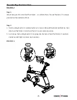
Page 5: ...using Qty 4 65 M8X70mm Screws Qty 8 78 M8X19mm Washer Qty 4 62 M8X 20mm Screw Make sure that the two Foot Tubes 5 6 which are with Foot Caps 28 and Ground Adjusters 29 are assembled onto the front and...

Page 6: ...ull the Locking Knob outward secondarily slide the Seat Post 2 into Main Frame 1 lastly release the Locking Knob 16 to spring into the hole of Seat Post and turn clockwise to lock tightly IMPORTANT Lo...

Page 7: ...of Right Crank 17 Secure in place by turning it clockwise to tighten Note Right Pedal 37 is marked with an R Step 2 Thread the Left Pedal 38 into the hole of Left Crank 18 Secure in place by turning...

Page 8: ...d on the underside of Seat Step 2 a Turn Locking Knob 16 counterclockwise to loosen then pull backward and hold on then slide Seat Post Slider 3 into Seat Post 2 to your desired position b Last releas...

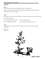
Page 9: ...88 in the main frame as shown in the diagram Step 2 Then slide the Console Tube 8 onto the Main Frame Assembly and secure each other by using the following spare parts Qty 3 64 M8 X60mm Allen Bolt Qt...

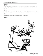
Page 10: ...lse Wires 90 into the hole of Console Tube 8 and pull it up to the top opening of Console Tube Step 2 Attach Handlebar 4 to Console Tube 8 using three Washers 78 and three Screws 59 Step 3 Then screw...

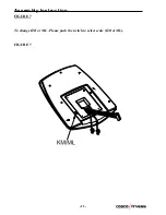
Page 11: ...11 Assembly Instruction FIGURE 7 To change KM or ML Please push the switch to select scale KM or ML FIGURE 7...

Page 12: ...lse Wires 90 and Extension Wire 89 to the wires out from Monitor 91 Then Secure Monitor 91 to the Console Tube 8 by using four Screws 67 Note The four Screws 67 will already be installed into the back...

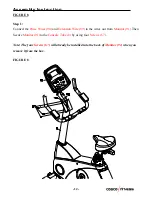
Page 13: ...bly Instruction FIGURE 9 The monitor only can be powered by using the AC adaptor input pls make sure the AC adapter has already been pluged into the adapter jack on the bottom housing as showed on the...

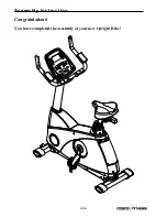
Page 14: ...14 Assembly Instruction Congratulations You have completed the assembly of your new Upright Bike...

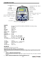
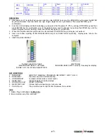
Page 15: ...LE BAR DISPLAY on Top of LCD screen USER see and follow up points of REVOLVING CIRC BAR DISPLAY step by step to operate this computer to finish inputting setting initial function mod and function valu...

Page 16: ...0 350 watts by using the UP DOWN knob To fix WATTS constant value and then press ST STOP key Use WATTS control mode to train yourself in different WATTS s constant PERSONAL Create your own Program pro...

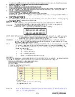
Page 17: ...s the ENTER key again for confirmation 3 When the Program and other protocols are entered press START STOP key and begin your workout 4 User can choose inputting PLUG IN RECEIVER and put on CHEST BELT...

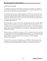
Page 18: ...r against your wrist over the main artery After finding your pulse count the number of beats in 10 seconds Multiply the number of beats by six to determine your pulse rate per minute We recommend taki...

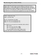
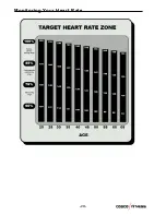
Page 19: ...h end or 75 of MHZ 30 year old THR Target Heart Rate would be 114 142 See Heart Rate Table on next page for additional calculations Fitness Safety The target heart rate chart indicates average rate zo...

Page 20: ...20 Monitoring Your Heart Rate...

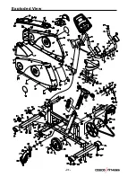
Page 21: ...21 Exploded View...

Page 22: ...tainer Ring Black 67 4 M5x10mm Metal Screw 22 2 Adjustment Channel 68 1 M20xP1 0x12t Hex Nylon Nut 23 1 V Belt 480J6 1222m m 69 2 M10 xP1 25R Nut Cap Licotted 24 2 1 1 4 Ball Plug 70 2 6mm Hex Nut Bla...

Reviews: