■
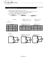
Output voltage is adjustable by the external resistor.
■
The temperature coefficient could become worse, depending on the type of a resistor.
Resistor
・・・・
Metal film type, coefficient of less than ±100ppm/
℃
■
When TRM is opened, output voltage is the minimum.
■
R
TRM
is calculated in the following expressions.
Table.5.1.1
Calculation result
Fig.5.1.1
Connecting
BRFS/BRDS 5-1
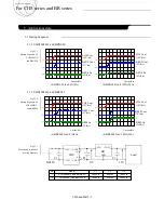
2.1 Pin configuration
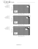
5. Adjustable voltage range
(a)BRFS30
(b)BRFS40
・
60S
・
120
・
150/
BRDS40
・
60S
・
120
・
150
+VOUT
+TRM
GND
Load
+S
R
TRM
BRFS30
]
[
8
.
0
8
Ω
k
VOUT
R
TRM
]
[
7
.
0
14
Ω
k
VOUT
R
TRM
]
[
6
.
0
12
Ω
k
VOUT
R
TRM
+VOUT
+TRM
GND
Load
+S
R
TRM
BRFS40
+VOUT
+TRM
GND
Load
+S
-S
R
TRM
-TRM
BRFS
50/50L/
60/100
No
VOUT
R
TRM
1
0.8
OPEN
2
1.0
40.0kΩ
3
1.2
20.0kΩ
4
1.5
11.429kΩ
5
1.8
8.0kΩ
6
2.5
4.706kΩ
7
3.3
3.2kΩ
No
VOUT
R
TRM
1
0.7
OPEN
2
1.0
46.6kΩ
3
1.2
28kΩ
4
1.5
17.5kΩ
5
1.8
12.7kΩ
No
VOUT
R
TRM
1
0.6
OPEN
2
1.0
30.0kΩ
3
1.2
20.0kΩ
4
1.5
13.3kΩ
5
1.8
10.0kΩ
(c)BRFS50
・
60
・
100/
BRDS60/100
(a)BRFS30
(c)BRFS50
・
60
・
100/
BRDS60/100
(a)BRFS30
Applications manual
For BRFS/BRDS series
(b)BRFS40
・
60S
・
120
・
150/
BRDS40
・
60S
・
120
・
150
(c)BRFS50
・
60
・
100/
BRDS60/100
(b)BRFS40
・
60S
・
120
・
150/
BRDS40
・
60S
・
120
・
150


