8.1
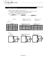
When the remote sensing function is not in use
Fig. 8.1.1
Connection
when the remote
sensing is not in use
■
When the remote sensing function is not in use, it is necessary to confirm that pins
are shorted bS and +VOUT ,and between -S and GND.
■
Wire bS and +VOUT ,and between -S and GND as short as possible.
Loop wiring should be avoided.
This power supply might become unstable by the noise coming from poor wiring.
8.2
When the remote sensing function is in use
Fig. 8.2.1
Connection
when the remote
sensing is in use
■
Twisted-pair wire or shield wire should be used for sensing wire.
■
Thick wire should be used for wiring between the power supply and a load.
Line drop should be less than 0.5V.
Voltage bVOUT and GND should remain within the output voltage adjustment range.
■
If the sensing patterns are short, heavy-current is drawn and the pattern may be damaged.
The pattern disconnection can be prevented by installing the protection parts as close
as possible to a load.
BRFS/BRDS 8-1
2.1 Pin configuration
8. Remote sensing
Applications manual
For BRFS/BRDS series


