vii
Table of Contents
HMI Error Codes ………………………..……………………………………………………….…………. 4-16
Standard Accessories ………….………………………..……………………………………………….…………… 4-17
Optional Accessories …….…….………………………..…………………………………………….……………… 4-18
Adjusting Wire Brush ………..……………………………………………………………………….………………. 4-20
Adjusting Coolant Flow ………..………..…………………………………………………………………..………. 4-20
Adjusting Blade Speed ………..………..……………………………………………………………………………. 4-21
Unrolling & Installing the Blade …………………………………………………………………….……………. 4-21
Cutting Operation ………..………..……………………………………………..……………………………………. 4-23
Breaking-In the Blade ………..………..…………………………………………………………………..…………. 4-24
Terminating a Cutting Operation ………..………..…………………………………….………………………. 4-24
Section 5 –
Electrical System
5-1
Electrical Circuit Diagrams ……….…………………..…………………………………………………………….. 5-2
Section 6 –
Hydraulic System
6-1
Hydraulic Diagrams ……….…………………..……………………………………………………………………….. 6-2
Section 7 –
Bandsaw Cutting: A Practical Guide
7-1
Introduction ……………………….…….…………………..……………………………………………………………. 7-1
Saw Blade Selection ………………….…………………..…………………………………………………………… 7-1
Some Sawing Practices …………….…………………..………………………………………….………………… 7-4
Saw Pitch Selection ……………………………………………………………………….……………….. 7-4
Material Size and Saw Pitch ………………………………………………….….……………………. 7-4
Section 8 –
Maintenance & Service
8-1
Introduction ……………………….…….…………………..……………………………………………………………. 8-1
Basic Maintenance ………………….…………………..…………………………………………….………………. 8-1
Maintenance Schedule …………….…………………..……………………………………………………………. 8-1
Before Beginning a Day’s Work ………………………………………………………………………. 8-2
After Ending a Day’s Work …………………………………………………….……………………….. 8-2
Every Month ………………………………………………………………………….………………………. 8-2
Every Three Months ………………..…………………………………………….………………………. 8-2
Every Six Months ……………….………………………………………………….………………………. 8-3
Storage Conditions …………………………....………..…………………………………………………………….. 8-3
Terminating the Use of Machine ……..…………..…………………………………………………………….. 8-3
Oil Recommendation for Maintenance ………………………………………………………………………. 8-4
Section 9 –
Troubleshooting
9-1
Introduction ……………………….…….…………………..……………………………………………………………. 9-1
Precautions ………………….…………………..……………………………………………………………………..... 9-2
Summary of Contents for SVT-6070H
Page 2: ... ...
Page 4: ... ...
Page 10: ... ...
Page 15: ...1 5 Illustration Emergency Stop Emergency Stop ...
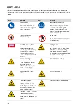
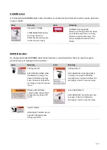
Page 20: ...1 10 Illustration Safety Labels ...
Page 25: ...2 3 MACHINE PARTS IDENTIFICATION ...
Page 26: ...2 4 FLOOR PLAN Machine top view Machine side view ...
Page 36: ... ...
Page 60: ... ...
Page 62: ...5 2 Fig 5 1 Control panel layout ...
Page 63: ...5 3 Fig 5 2 Circuit board layout ...
Page 64: ...5 4 Fig 5 3 Power supply layout ...
Page 65: ...5 5 Fig 5 4 PLC I O layout ...
Page 66: ... ...
Page 67: ...6 1 Section 6 HYDRAULIC SYSTEM HYDRAULIC DIAGRAM ...
Page 68: ...6 2 Fig 6 1 Hydraulic layout ...
Page 104: ... ...
Page 105: ... ...


